1.5µA I , Step-Up DC-DC Converters
Q
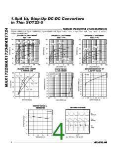
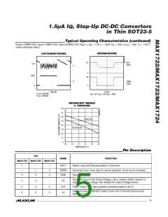
in Thin SOT23-5
For maximum output current, choose the inductor value
so that the controller reaches the current-limit before
the maximum on-time is triggered:
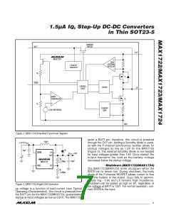
INPUT
0.8V TO V
10µH
OUT
V
t
BATT ON(MAX)
OUTPUT
2V TO 5.5V
L <
10µF
BATT
LX
I
LIM
OUT
where the maximum on-time is typically 5µs, and the
current limit (I
) is typically 500mA (see Electrical
LIM
R2
R1
MAX1722
10µF
Characteristics table).
FB
For larger inductor values, determine the peak inductor
current (I
by:
PEAK)
GND
V
t
BATT ON(MAX)
L
I
=
PEAK
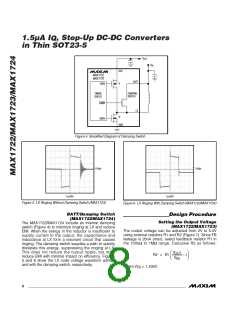
Figure 7. Adjustable Output Circuit
INPUT
Inductor Selection
10µH
0.8V TO V
OUT
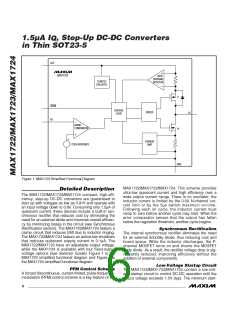
The control scheme of the MAX1722/MAX1723/
MAX1724 permits flexibility in choosing an inductor. A
10µH inductor value performs well in most applications.
Smaller inductance values typically offer smaller physi-
cal size for a given series resistance, allowing the
smallest overall circuit dimensions. Circuits using larger
inductance values may start up at lower battery volt-
ages, provide higher efficiency, and exhibit less ripple,
but they may reduce the maximum output current. This
occurs when the inductance is sufficiently large to pre-
C1
10µF
BATT
LX
OUTPUT
OUT (NOM)
OUT
V
MAX1724
C2
10µF
ON
OFF
SHDN
GND
vent the maximum current limit (I
) from being
LIM
reached before the maximum on-time (t
expires.
)
ON(MAX)
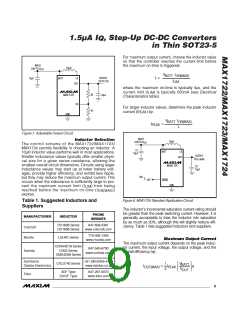
Figure 8. MAX1724 Standard Application Circuit
Table 1. Suggested Inductors and
Suppliers
The inductor’s incremental saturation current rating should
be greater than the peak switching current. However, it is
generally acceptable to bias the inductor into saturation
by as much as 20%, although this will slightly reduce effi-
ciency. Table 1 lists suggested inductors and suppliers.
PHONE
MANUFACTURER
Coilcraft
INDUCTOR
WEBSITE
DO1608 Series
DO1606 Series
847-639-2361
www.coilcraft.com
770-436-1300
www.murata.com
Murata
LQH4C Series
Maximum Output Current
The maximum output current depends on the peak induc-
tor current, the input voltage, the output voltage, and the
overall efficiency (η):
CDRH4D18 Series
CR32 Series
CMD4D06 Series
847-545-6700
www.sumida.com
Sumida
Sumitomo/
Daidoo Electronics
+81 (06) 6355-5733
www.daidoo.co.jp
CXLD140 Series
V
V
1
2
BATT
I
=
I
η
OUT(MAX)
PEAK
OUT
3DF Type
D412F Type
847-297-0070
www.toko.com
Toko
_______________________________________________________________________________________
9

 MAXIM [ MAXIM INTEGRATED PRODUCTS ]