1.5µA I , Step-Up DC-DC Converters
Q
in Thin SOT23-5
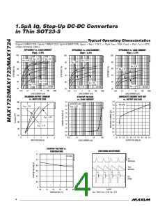
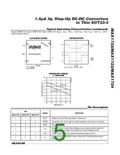
Typical Operating Characteristics (continued)
(Figure 3 (MAX1723), Figure 7 (MAX1722), Figure 8 (MAX1724), V
unless otherwise noted.)
= V = 1.5V, L = 10µH, C = 10µF, C
= 10µF, T = +25°C,
OUT A
BATT
IN
IN
SHUTDOWN RESPONSE
LOAD-TRANSIENT RESPONSE
V
5V
OUT
3.3V
2V/div
A
0
50mA
2V
B
V
SHDN
1V/div
0
0
1ms/div
200µs/div
A: V , 50mV/div
OUT
OUT
V
IN
= 3.3V, V
= 5.0V, R
= 100Ω
OUT
OUT
B: I , 20mA/div
SHUTDOWN INPUT THRESHOLD
vs. TEMPERATURE
0.8
0.7
0.6
0.5
0.4
0.3
0.2
0.1
0
RISING EDGE
FALLING EDGE
-40
-15
10
35
60
85
TEMPERATURE (°C)
Pin Description
PIN
NAME
FUNCTION
Battery Input and Damping Switch Connection
MAX1722
MAX1723
MAX1724
1
—
2
—
1
1
3
2
BATT
SHDN
GND
Shutdown Input. Drive high for normal operation. Drive low for shutdown.
Ground
2
Feedback Input to Set Output Voltage. Use a resistor-divider network to
adjust the output voltage. See Setting the Output Voltage section.
3
4
5
3
4
5
—
4
FB
OUT
LX
Power Output. OUT also provides bootstrap power to the IC.
Internal N-channel MOSFET Switch Drain and P-Channel Synchronous
Rectifier Drain
5
_______________________________________________________________________________________
5

 MAXIM [ MAXIM INTEGRATED PRODUCTS ]