Complete, Isolated RS-485/RS-422
Data Interface
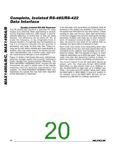
Connections and components from one side should
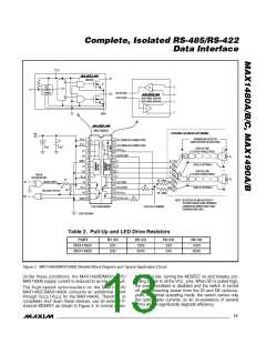
The DI and DE (MAX1480A/B/C only) inputs are the
cathodes of LEDs whose anodes are connected to the
supply. These points are best driven by a CMOS-logic
gate with a series resistor to limit the current. The resis-
tor values shown in Tables 1 and 2 are recommended
when the 74HC86 gate or equivalent is used. These
values may need to be adjusted if a driving gate with
dissimilar series resistance is used.
not be located near those of the other side.
• A shield trace connected to the ground on each side
of the barrier can help intercept capacitive currents
that might otherwise couple into the signal path. In a
double-sided or multilayer board, these shield traces
should be present on all conductor layers.
• Try to maximize the width of the isolation barrier
wherever possible; a clear space of at least 0.25
inches between ground and isolated common is
suggested.
All pull-up resistors are based on optocoupler specifica-
tions in order to optimize the devices’ data-transfer rates.
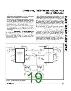
Isolated Common Connection
The isolated common may be completely floating with
respect to the logic ground and the effective network
ground. The receiver input resistors will cause the iso-
lated common voltage to go to the mean voltage of the
receiver inputs. If using shielded cable, connect the
isolated common to the shield through a 100Ω resistor.
In the case of the MAX1490, each shield should have
its own 100Ω resistor (Figures 1, 2, 13, and 14).
Pullup and LED Drive Resistors
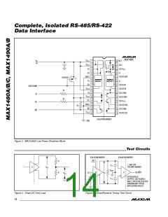
The MAX1480A/MAX1480B/MAX1480C/MAX1490A/
MAX1490B are specified and characterized using the
resistor values shown in Table 1 of Figure 1 and Table
2 of Figure 2. Altering the recommended values can
degrade performance.
+5V
+5V
NETWORK SEGMENT B
2 8 10 14
NETWORK SEGMENT A
2 8 10 14
13
3kΩ
200Ω
A
B
23
25
23
25
A
1
2
9
B
26
26
3kΩ
74HC04
MAX1480C
MAX1480C
3kΩ
200Ω
3kΩ
4
3
13
11
9
19
22
17
21
19
22
17
21
3kΩ
3kΩ
DRIVER
ENABLE
B > A
DRIVER
ENABLE
A > B
200Ω
200Ω
11
24
24
200Ω
200Ω
15
15
5 7 12
5 7 12
+5V
+5V
51kΩ 1000pF
51kΩ 1000pF
16 15 14
7
6
5
2
B
Q
Q
10
B
Q
13
4
74HC123
74HC123
Q 12
1 A
9
A
CLR
3
CLR
11
Figure 15. Doubly Isolated RS-485 Repeater
______________________________________________________________________________________ 19

 MAXIM [ MAXIM INTEGRATED PRODUCTS ]