Complete, Isolated RS-485/RS-422
Data Interface
MAX1480B/MAX1480C/MAX1490B:
_____________________Function Tables
Reduced EMI and Reflections
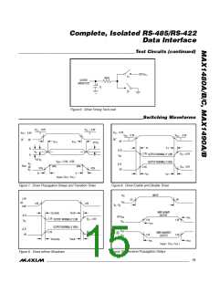
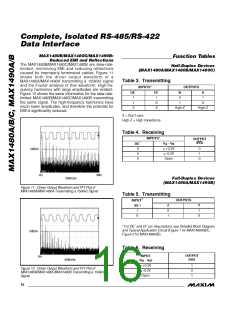
The MAX1480B/MAX1480C/MAX1490B are slew-rate-
limited, minimizing EMI and reducing reflections
caused by improperly terminated cables. Figure 11
shows both the driver output waveform of a
MAX1480A/MAX1490A transmitting a 150kHz signal
and the Fourier analysis of that waveform. High-fre-
quency harmonics with large amplitudes are evident.
Figure 12 shows the same information for the slew-rate-
limited MAX1480B/MAX1480C/MAX1490B transmitting
the same signal. The high-frequency harmonics have
much lower amplitudes, and therefore the potential for
EMI is significantly reduced.
Half-Duplex Devices
(MAX1480A/MAX1480B/MAX1480C)
Table 3. Transmitting
INPUTS*
OUTPUTS
B
0
1
A
1
DE´
1
DI´
1
1
0
0
0
X
High-Z
High-Z
X = Don’t care
High-Z = High impedance
Table 4. Receiving
INPUTS*
OUTPUT
(RO)
V
- V
B
DE´
0
A
≥ +0.2V
≤ -0.2V
Open
0
1
0
10dB/div
0
0
0Hz
5MHz
500kHz/div
Full-Duplex Devices
(MAX1490A/MAX1490B)
Figure 11. Driver Output Waveform and FFT Plot of
MAX1480A/MAX1490A Transmitting a 150kHz Signal
Table 5. Transmitting
OUTPUTS
INPUT*
Z
0
1
Y
1
0
(DI´)
1
0
* For DE´ and DI´ pin descriptions, see Detailed Block Diagram
and Typical Application Circuit (Figure 1 for MAX1480A/B/C,
Figure 2 for MAX1490A/B).
10dB/div
Table 6. Receiving
OUTPUT
(RO)
INPUT
(V - V )
0Hz
5MHz
500kHz/div
A
B
≥ +0.2V
≤ -0.2V
Open
1
0
1
Figure 12. Driver Output Waveform and FFT Plot of
MAX1480B/MAX1480C/MAX1490B Transmitting a 150kHz
Signal
16 ______________________________________________________________________________________

 MAXIM [ MAXIM INTEGRATED PRODUCTS ]