MAX11120–MAX11128
1Msps, Low-Power, Serial 12-/10-/8-Bit,
4-/8-/16-Channel ADCs
AutoShutdown with External Clock Mode
When the PM_ bits in the ADC Mode Control register are
asserted (Table 5), the device shuts down at the rising
edge of CS in the next frame. The device powers up
again at the following falling edge of CS. There are two
available options:
Power-Down Mode
The MAX11120–MAX11128 feature three power-down
modes.
Static Shutdown
The devices shut down when the SPM bits in the ADC
Configuration register are asserted (Table 6). There are
two shutdown options:
U AutoShutdown where all circuitry is shutdown.
U AutoStandby where all circuitry are powered down
UFull shutdown where all circuitry is shutdown.
except for the internal bias generator.
UPartial shutdown where all circuitry is powered down
AutoShutdown with Internal Clock Mode
The device shuts down after all conversions are complet-
ed. The device powers up again at the next falling edge
of CNVST or at the rising edge of CS after the SWCNV
bit is asserted.
except for the internal bias generator.
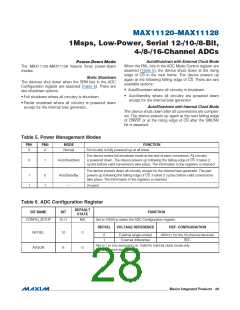
Table 5. Power Management Modes
PM1
PM0
MODE
FUNCTION
0
0
Normal
All circuitry is fully powered up at all times.
The device enters full shutdown mode at the end of each conversion. All circuitry
is powered down. The device powers up following the falling edge of CS. It takes 2
cycles before valid conversions take place. The information in the registers is retained.
0
1
AutoShutdown
The device powers down all circuitry except for the internal bias generator. The part
powers up following the falling edge of CS. It takes 2 cycles before valid conversions
take place. The information in the registers is retained.
1
1
0
1
AutoStandby
—
Unused.
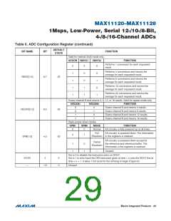
Table 6. ADC Configuration Register
DEFAULT
STATE
BIT NAME
BIT
FUNCTION
CONFIG_SETUP
15:11
N/A
Set to 10000 to select the ADC Configuration register.
REFSEL
VOLTAGE REFERENCE
REF- CONFIGURATION
REFSEL
AVGON
10
9
0
0
0
1
External single-ended
External differential
AIN15 ( for the 16-channel devices)
REF-
Set to 1 to turn averaging on. Valid for internal clock mode only.
Set to 0 to turn averaging off.
���������������������������������������������������������������� Maxim Integrated Products 28

 MAXIM [ MAXIM INTEGRATED PRODUCTS ]