MAX11120–MAX11128
1Msps, Low-Power, Serial 12-/10-/8-Bit,
4-/8-/16-Channel ADCs
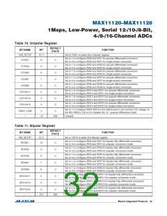
Table 10. Unipolar Register
DEFAULT
STATE
BIT NAME
UNI_SETUP
UCH0/1
BIT
15:11
10
FUNCTION
Set to 10001 to select the Unipolar register.
—
Set to 1 to configure AIN0 and AIN1 for pseudo-differential conversion.
Set to 0 to configure AIN0 and AIN1 for single-ended conversion.
0
Set to 1 to configure AIN2 and AIN3 for pseudo-differential conversion.
Set to 0 to configure AIN2 and AIN3 for single-ended conversion.
Set to 1 to configure AIN4 and AIN5 for pseudo-differential conversion.
Set to 0 to configure AIN4 and AIN5 for single-ended conversion.
UCH2/3
UCH4/5
9
8
7
6
5
4
3
0
0
0
0
0
0
0
Set to 1 to configure AIN6 and AIN7 for pseudo-differential conversion.
Set to 0 to configure AIN6 and AIN7 for single-ended conversion.
UCH6/7
Set to 1 to configure AIN8 and AIN9 for pseudo-differential conversion.
Set to 0 to configure AIN8 and AIN9 for single-ended conversion.
Set to 1 to configure AIN10 and AIN11 for pseudo-differential conversion.
Set to 0 to configure AIN10 and AIN11 for single-ended conversion.
Set to 1 to configure AIN12 and AIN13 for pseudo-differential conversion.
Set to 0 to configure AIN12 and AIN13 for single-ended conversion.
Set to 1 to configure AIN14 and AIN15 for pseudo-differential conversion.
Set to 0 to configure AIN14 and AIN15 for single-ended conversion.
UCH8/9
UCH10/11
UCH12/13
UCH14/15
Set to 1 to configure AIN0–AIN14 to be referenced to one common DC voltage on
the REF-/AIN15. Set to 0 to disable the 15:1 pseudo differential mode.
PDIFF_COM
—
2
0
1:0
000
Unused.
Table 11. Bipolar Register
DEFAULT
STATE
BIT NAME
BIP_SETUP
BCH0/1
BIT
15:11
10
FUNCTION
—
Set to 10010 to select the Bipolar register.
Set to 1 to configure AIN0 and AIN1 for bipolar fully differential conversion.
Set to 0 to configure AIN0 and AIN1 for unipolar conversion mode.
0
Set to 1 to configure AIN2 and AIN3 for bipolar fully differential conversion.
Set to 0 to configure AIN2 and AIN3 for unipolar conversion mode.
BCH2/3
BCH4/5
9
8
7
6
5
4
0
0
0
0
0
0
Set to 1 to configure AIN4 and AIN5 for bipolar fully differential conversion.
Set to 0 to configure AIN4 and AIN5 for unipolar conversion mode.
Set to 1 to configure AIN6 and AIN7 for bipolar fully differential conversion.
Set to 0 to configure AIN6 and AIN7 for unipolar conversion mode.
BCH6/7
Set to 1 to configure AIN8 and AIN9 for bipolar fully differential conversion.
Set to 0 to configure AIN8 and AIN9 for unipolar conversion mode.
BCH8/9
Set to 1 to configure AIN10 and AIN11 for bipolar fully differential conversion.
Set to 0 to configure AIN10 and AIN11 for unipolar conversion mode.
BCH10/11
BCH12/13
Set to 1 to configure AIN12 and AIN13 for bipolar fully differential conversion.
Set to 0 to configure AIN12 and AIN13 for unipolar conversion mode.
Set to 1 to configure AIN14 and AIN15 for bipolar fully differential conversion.
Set to 0 to configure AIN14 and AIN15 for unipolar conversion mode.
BCH14/15
—
3
0
2:0
000
Unused.
���������������������������������������������������������������� Maxim Integrated Products 32

 MAXIM [ MAXIM INTEGRATED PRODUCTS ]