Chopper-Stabilized Op Amps
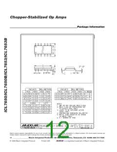
The 14-pin DIP configuration has been specifically
designed to ease input guarding. The pins adjacent to
the inputs are not used.
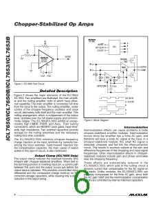
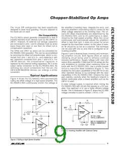
the amplifier’s inverting input, integrate the error, and
drive the amplifier’s noninverting input to correct for the
offset voltage detected at the inverting input. The cir-
cuit’s DC offset characteristics are determined by the
ICL7650/ICL7653, and its AC performance is deter-
mined by the high-speed amplifier. While this circuit
continuously and automatically adjusts the amplifier’s
offset to less than 5µV, it does not correct for errors
caused by the input bias current, so the value of resis-
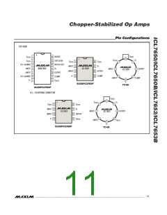
Pin Compatibility
The ICL7653’s pinout generally corresponds to that of
industry-standard 8-pin devices such as the LM741 or
LM101. However, its external null storage capacitors
are connected to pins 1 and 8; whereas most op amps
leave these pins open or use them for offset null or
compensation capacitors.
tor R should be as low as is practical. This technique
F
can be used with any op amp that is configured as an
inverting amplifier.
The OP05 and OP07 op amps can be converted for
ICL7650/ICL7653 operation. This can be accomplished
by removing the offset null potentiometer, which is con-
nected from pins 1 and 8 to V+, and replacing it with
two capacitors connected from pins 1 and 8 to V-. For
LM108 devices, the compensation capacitor is
replaced by the external nulling capacitors. Pin 5 is the
output clamp connection on the ICL7650/ICL7653. By
removing any circuit connections from this pin, the
LM101/LM748/LM709 devices can undergo a similar
conversion.
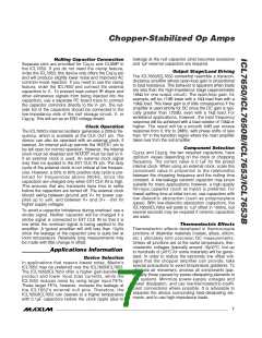
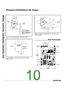
Figures 5 and 6 illustrate basic inverting and noninvert-
ing amplifier circuits. Both figures show an output
clamping circuit being used to enhance overload
recovery performance. Supply voltage ( 8V max) and
output drive capability (10kΩ load for full swing) are the
only limitations to consider when replacing other op
amps with the ICL7650/ICL7653. Use a simple booster
circuit to overcome these limitations (Figure 7). This
enables the full output capabilities of the LM118 (or any
other standard device) to be combined with the input
capabilities of the ICL7650/ICL7653. Observe the loop
gain stability carefully when the feedback network is
added, particularly when a slower amplifier such as the
LM741 is used.
Typical Applications
Figure 4 shows the ICL7650/ICL7653 automatically
nulling the offset voltage of a high-speed amplifier. The
ICL7650/ICL7653 continuously monitor the voltage at
A lower voltage supply is required when mixing the
ICL7650/ICL7653 with circuits that operate at 15V sup-
plies. One approach is to use a highly efficient voltage
divider. This is illustrated in Figure 8, where the ICL7660
voltage converter is used to convert +15V to +7.5V.
R
F
R
IN
R2
V
HIGH-
SPEED
AMP
OUT
CLAMP
R1
1k
INPUT
OUTPUT
ICL7650
47Ω
10k
C
(R1 || R2) ≥ 100kΩ
FOR FULL CLAMP EFFECT
R
0.1µF
100k
C
NOTE: R1 || R2 INDICATES THE
PARALLEL COMBINATION OF
R1 || R2.
0.1µF 0.1µF
ICL7650
ICL7653
Figure 5. Inverting Amplifier with Optional Clamp
Figure 4. Nulling a High-Speed Amplifier
_______________________________________________________________________________________
9

 MAXIM [ MAXIM INTEGRATED PRODUCTS ]