1024-Bit, 1-Wire EEPROM
for Automotive Applications
8
5
4
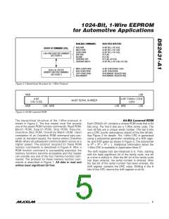
POLYNOMIAL = X + X + X + 1
1ST
2ND
3RD
4TH
5TH
6TH
7TH
8TH
STAGE
STAGE
STAGE
STAGE
STAGE
STAGE
STAGE
STAGE
0
1
2
3
4
5
6
7
8
X
X
X
X
X
X
X
X
X
INPUT DATA
DS243-A1
Figure 4. 1-Wire CRC Generator
EPROM mode by setting the associated protection byte
in the register row. The last two rows contain protection
registers and reserved bytes. The register row consists
of four protection control bytes, a copy protection byte,
the factory byte, and two user byte/manufacture ID
bytes. The manufacturer ID can be a customer-sup-
plied identification code that assists the application
software in identifying the product the DS2431-A1 is
associated with. Contact the factory to set up and reg-
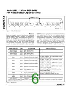
Memory
Data memory and registers are located in a linear
address space, as shown in Figure 5. The data memory
and the registers have unrestricted read access. The
DS2431-A1 EEPROM array consists of 18 rows of 8
bytes each. The first 16 rows are divided equally into
four memory pages (32 bytes each). These four pages
are the primary data memory. Each page can be indi-
vidually set to open (unprotected), write protected, or
ADDRESS RANGE
0000h to 001Fh
0020h to 003Fh
0040h to 005Fh
0060h to 007Fh
TYPE
R/(W)
R/(W)
R/(W)
R/(W)
DESCRIPTION
Data Memory Page 0
Data Memory Page 1
Data Memory Page 2
Data Memory Page 3
PROTECTION CODES
—
—
—
—
55h: Write Protect P0; AAh: EPROM Mode P0; 55h
or AAh: Write Protect 80h
*
0080h
R/(W)
R/(W)
R/(W)
R/(W)
R/(W)
R
Protection Control Byte Page 0
Protection Control Byte Page 1
Protection Control Byte Page 2
Protection Control Byte Page 3
Copy Protection Byte
55h: Write Protect P1; AAh: EPROM Mode P1; 55h
or AAh: Write Protect 81h
*
0081h
55h: Write Protect P2; AAh: EPROM Mode P2; 55h
or AAh: Write Protect 82h
*
0082h
55h: Write Protect P3; AAh: EPROM Mode P3; 55h
or AAh: Write Protect 83h
*
0083h
55h or AAh: Copy Protect 0080:008Fh, and Any
Write-Protected Pages
*
0084h
AAh: Write Protect 85h, 86h, 87h;
55h: Write Protect 85h, Unprotect 86h, 87h
0085h
Factory Byte. Set at Factory.
0086h
0087h
R/(W)
R/(W)
N/A
User Byte/Manufacturer ID
User Byte/Manufacturer ID
Reserved
—
—
—
0088h to 008Fh
* Once programmed to AAh or 55h this address becomes read-only. All other codes can be stored, but neither write protect the
address nor activate any function.
Figure 5. Memory Map
6
_______________________________________________________________________________________

 MAXIM [ MAXIM INTEGRATED PRODUCTS ]