1024-Bit, 1-Wire EEPROM
for Automotive Applications
DS243-A1
AVAILABLE COMMANDS:
DATA FIELD AFFECTED:
READ ROM
64-BIT REG. #, RC-FLAG
64-BIT REG. #, RC-FLAG
64-BIT REG. #, RC-FLAG
RC-FLAG
DS2431-A1 COMMAND LEVEL:
MATCH ROM
SEARCH ROM
SKIP ROM
1-Wire ROM FUNCTION COMMANDS
(SEE FIGURE 9)
RESUME
RC-FLAG
OVERDRIVE SKIP
OVERDRIVE MATCH
RC-FLAG, OD-FLAG
64-BIT REG. #, RC-FLAG, OD-FLAG
WRITE SCRATCHPAD
READ SCRATCHPAD
COPY SCRATCHPAD
READ MEMORY
64-BIT SCRATCHPAD, FLAGS
64-BIT SCRATCHPAD
DATA MEMORY, REGISTER PAGE
DATA MEMORY, REGISTER PAGE
DS2431-A1-SPECIFIC
MEMORY FUNCTION COMMANDS
(SEE FIGURE 7)
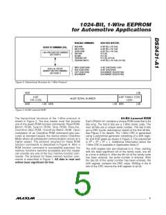
Figure 2. Hierarchical Structure for 1-Wire Protocol
MSB
LSB
8-BIT
CRC CODE
8-BIT FAMILY CODE
(2Dh)
48-BIT SERIAL NUMBER
MSB
LSB MSB
LSB MSB
LSB
Figure 3. 64-Bit Lasered ROM
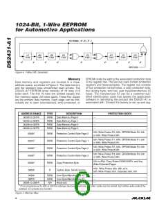
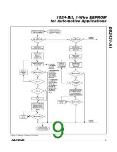
The hierarchical structure of the 1-Wire protocol is
shown in Figure 2. The bus master must first provide
one of the seven ROM function commands: Read ROM,
Match ROM, Search ROM, Skip ROM, Resume,
Overdrive Skip ROM, Overdrive Match ROM. Upon
completion of an Overdrive ROM command byte exe-
cuted at standard speed, the device enters Overdrive
Mode where all subsequent communication occurs at a
higher speed. The protocol required for these ROM
function commands is described in Figure 9. After a
ROM function command is successfully executed, the
memory functions become accessible and the master
can provide any one of the four memory function com-
mands. The protocol for these memory function com-
mands is described in Figure 7. All data is read and
written least significant bit first.
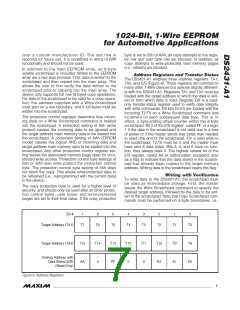
64-Bit Lasered ROM
Each DS2431-A1 contains a unique ROM code that is 64
bits long. The first 8 bits are a 1-Wire family code. The
next 48 bits are a unique serial number. The last 8 bits
are a CRC (cyclic redundancy check) of the first 56 bits.
See Figure 3 for details. The 1-Wire CRC is generated
using a polynomial generator consisting of a shift regis-
ter and XOR gates as shown in Figure 4. The polynomial
8
5
4
is X + X + X + 1. Additional information about the
1-Wire CRC is available in Application Note 27.
The shift register bits are initialized to 0. Then, starting
with the least significant bit of the family code, one bit
at a time is shifted in. After the 8th bit of the family code
has been entered, the serial number is entered. After
the last bit of the serial number has been entered, the
shift register contains the CRC value. Shifting in the 8
bits of the CRC returns the shift register to all 0s.
_______________________________________________________________________________________
5

 MAXIM [ MAXIM INTEGRATED PRODUCTS ]