1024-Bit, 1-Wire EEPROM
for Automotive Applications
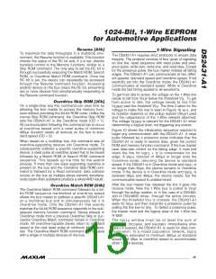
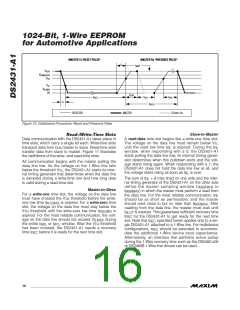
MASTER Tx "RESET PULSE"
MASTER Rx "PRESENCE PULSE"
ε
t
MSP
V
PUP
V
IHMASTER
V
TH
V
TL
V
ILMAX
0V
t
PDH
t
t
t
REC
RSTL
PDL
DS243-A1
t
F
t
RSTH
RESISTOR
MASTER
DS2431-A1
Figure 10. Initialization Procedure: Reset and Presence Pulse
Slave-to-Master
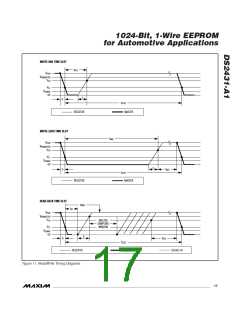
Read-/Write-Time Slots
Data communication with the DS2431-A1 takes place in
time slots, which carry a single bit each. Write-time slots
transport data from bus master to slave. Read-time slots
transfer data from slave to master. Figure 11 illustrates
the definitions of the write- and read-time slots.
A read-data time slot begins like a write-one time slot.
The voltage on the data line must remain below V
TL
until the read low time t
is expired. During the t
RL
RL
window, when responding with a 0, the DS2431-A1
starts pulling the data line low; its internal timing gener-
ator determines when this pulldown ends and the volt-
age starts rising again. When responding with a 1, the
DS2431-A1 does not hold the data line low at all, and
All communication begins with the master pulling the
data line low. As the voltage on the 1-Wire line falls
below the threshold V , the DS2431-A1 starts its inter-
TL
nal timing generator that determines when the data line
is sampled during a write-time slot and how long data
is valid during a read-time slot.
the voltage starts rising as soon as t is over.
RL
The sum of t + δ (rise time) on one side and the inter-
nal timing generator of the DS2431-A1 on the other side
RL
define the master sampling window (t
to
MSRMIN
Master-to-Slave
t
) in which the master must perform a read from
MSRMAX
For a write-one time slot, the voltage on the data line
the data line. For the most reliable communication, t
RL
must have crossed the V threshold before the write-
TH
should be as short as permissible, and the master
should read close to but no later than t . After
one low time t
is expired. For a write-zero time
W1LMAX
MSRMAX
slot, the voltage on the data line must stay below the
threshold until the write-zero low time t is
reading from the data line, the master must wait until
V
TH
W0LMIN
t
t
is expired. This guarantees sufficient recovery time
for the DS2431-A1 to get ready for the next time
SLOT
REC
expired. For the most reliable communication, the volt-
age on the data line should not exceed V during
ILMAX
slot. Note that t
specified herein applies only to a sin-
gle DS2431-A1 attached to a 1-Wire line. For multidevice
configurations, t should be extended to accommo-
date the additional 1-Wire device input capacitance.
Alternatively, an interface that performs active pullup
during the 1-Wire recovery time such as the DS2482-x00
or DS2480B 1-Wire line drivers can be used.
REC
the entire t
or t
window. After the V threshold
W1L TH
W0L
has been crossed, the DS2431-A1 needs a recovery
time t before it is ready for the next time slot.
REC
REC
16 ______________________________________________________________________________________

 MAXIM [ MAXIM INTEGRATED PRODUCTS ]