1024-Bit, 1-Wire EEPROM
for Automotive Applications
DS243-A1
Resume [A5h]
1-Wire Signaling
To maximize the data throughput in a multidrop envi-
ronment, the Resume function is available. This function
checks the status of the RC bit and, if it is set, directly
transfers control to the Memory functions, similar to a
Skip ROM command. The only way to set the RC bit is
through successfully executing the Match ROM, Search
ROM, or Overdrive Match ROM command. Once the
RC bit is set, the device can repeatedly be accessed
through the Resume command function. Accessing
another device on the bus clears the RC bit, preventing
two or more devices from simultaneously responding to
the Resume command function.
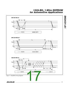
The DS2431-A1 requires strict protocols to ensure data
integrity. The protocol consists of four types of signaling
on one line: reset sequence with reset pulse and pres-
ence pulse, write-zero, write-one, and read-data. Except
for the presence pulse, the bus master initiates all falling
edges. The DS2431-A1 can communicate at two differ-
ent speeds: standard speed and overdrive speed. If not
explicitly set into the Overdrive mode, the DS2431-A1
communicates at standard speed. While in Overdrive
mode the fast timing applies to all waveforms.
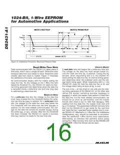
To get from idle to active, the voltage on the 1-Wire line
needs to fall from V
below the threshold V . To get
TL
PUP
Overdrive Skip ROM [3Ch]
On a single-drop bus this command can save time by
allowing the bus master to access the memory func-
tions without providing the 64-bit ROM code. Unlike the
normal Skip ROM command, the Overdrive Skip ROM
sets the DS2431-A1 in the Overdrive mode (OD = 1).
All communication following this command has to occur
at overdrive speed until a reset pulse of minimum
480µs duration resets all devices on the bus to stan-
dard speed (OD = 0).
from active to idle, the voltage needs to rise from
past the threshold V . The time it takes for the
V
ILMAX
TH
voltage to make this rise is seen in Figure 10 as ε, and
its duration depends on the pullup resistor (R ) used
PUP
and the capacitance of the 1-Wire network attached.
The voltage V
is relevant for the DS2431-A1 when
ILMAX
determining a logical level, not triggering any events.
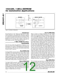
Figure 10 shows the initialization sequence required to
begin any communication with the DS2431-A1. A reset
pulse followed by a presence pulse indicates that the
DS2431-A1 is ready to receive data, given the correct
ROM and memory function command. If the bus master
uses slew-rate control on the falling edge, it must pull
When issued on a multidrop bus, this command sets all
overdrive-supporting devices into Overdrive mode. To
subsequently address a specific overdrive-supporting
device, a reset pulse at overdrive speed has to be issued
followed by a Match ROM or Search ROM command
sequence. This speeds up the time for the search
process. If more than one slave supporting overdrive is
present on the bus and the Overdrive Skip ROM com-
mand is followed by a Read command, data collision
occurs on the bus as multiple slaves transmit simultane-
ously (open-drain pulldowns produce a wired-AND result).
down the line for t
+ t to compensate for the
F
RSTL
edge. A t
duration of 480µs or longer exits the
RSTL
Overdrive mode, returning the device to standard
speed. If the DS2431 is in Overdrive mode and t is
RSTL
no longer than 80µs, the device remains in Overdrive
mode. If the device is in Overdrive mode and t is
RSTL
between 80µs and 480µs, the device resets, but the
communication speed is undetermined.
After the bus master has released the line it goes into
Overdrive Match ROM [69h]
The Overdrive Match ROM command followed by a 64-
bit ROM sequence transmitted at overdrive speed
allows the bus master to address a specific DS2431-A1
on a multidrop bus and to simultaneously set it in
Overdrive mode. Only the DS2431-A1 that exactly
matches the 64-bit ROM sequence responds to the sub-
sequent memory function command. Slaves already in
Overdrive mode from a previous Overdrive Skip or suc-
cessful Overdrive Match command remain in Overdrive
mode. All overdrive-capable slaves return to standard
speed at the next reset pulse of minimum 480µs dura-
tion. The Overdrive Match ROM command can be used
with a single or multiple devices on the bus.
receive mode. Now the 1-Wire bus is pulled to V
PUP
through the pullup resistor, or in the case of a DS2482-
x00 or DS2480B driver, through the active circuitry.
When the threshold V
is crossed, the DS2431-A1
TH
waits for t
and then transmits a presence pulse by
PDH
pulling the line low for t
. To detect a presence pulse,
PDL
the master must test the logical state of the 1-Wire line
at t
.
MSP
The t
window must be at least the sum of
RSTH
t
t
, t
, and t
. Immediately after
RECMIN
PDHMAX PDLMAX
RSTH
munication. In a mixed population network, t
is expired, the DS2431-A1 is ready for data com-
RSTH
should be extended to minimum 480µs at standard
speed and 48µs at overdrive speed to accommodate
other 1-Wire devices.
______________________________________________________________________________________ 15

 MAXIM [ MAXIM INTEGRATED PRODUCTS ]