1024-Bit, 1-Wire EEPROM
for Automotive Applications
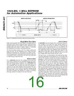
V
PUP
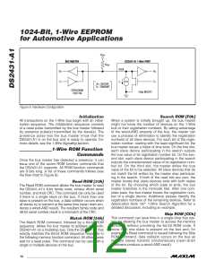
BUS MASTER
DS2431-A1 1-Wire PORT
R
PUP
DATA
Rx
Tx
Rx
Tx
I
L
Rx = RECEIVE
Tx = TRANSMIT
DS243-A1
OPEN-DRAIN
PORT PIN
100Ω MOSFET
Figure 8. Hardware Configuration
Initialization
Search ROM [F0h]
All transactions on the 1-Wire bus begin with an initial-
ization sequence. The initialization sequence consists
of a reset pulse transmitted by the bus master followed
by presence pulse(s) transmitted by the slave(s). The
presence pulse lets the bus master know that the
DS2431-A1 is on the bus and is ready to operate. For
more details, see the 1-Wire Signaling section.
When a system is initially brought up, the bus master
might not know the number of devices on the 1-Wire
bus or their registration numbers. By taking advantage
of the wired-AND property of the bus, the master can
use a process of elimination to identify the registration
numbers of all slave devices. For each bit of the regis-
tration number, starting with the least significant bit, the
bus master issues a triplet of time slots. On the first slot,
each slave device participating in the search outputs
the true value of its registration number bit. On the sec-
ond slot, each slave device participating in the search
outputs the complemented value of its registration num-
ber bit. On the third slot, the master writes the true
value of the bit to be selected. All slave devices that do
not match the bit written by the master stop participat-
ing in the search. If both of the read bits are zero, the
master knows that slave devices exist with both states
of the bit. By choosing which state to write, the bus
master branches in the romcode tree. After one com-
plete pass, the bus master knows the registration num-
ber of a single device. Additional passes identify the
registration numbers of the remaining devices. Refer to
Application Note 187: 1-Wire Search Algorithm for a
detailed discussion, including an example.
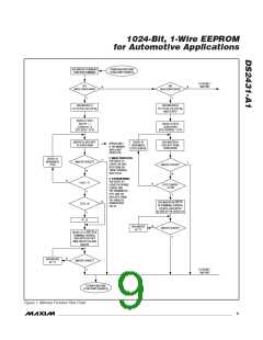
1-Wire ROM Function
Commands
Once the bus master has detected a presence, it can
issue one of the seven ROM function commands that
the DS2431-A1 supports. All ROM function commands
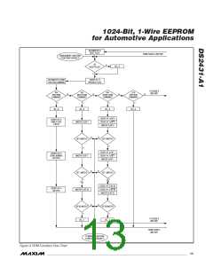
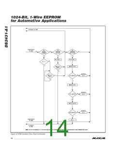
are 8 bits long. A list of these commands follows (see
the flow chart in Figure 9).
Read ROM [33h]
The Read ROM command allows the bus master to read
the DS2431-A1’s 8-bit family code, unique 48-bit serial
number, and 8-bit CRC. This command can only be used
if there is a single slave on the bus. If more than one
slave is present on the bus, a data collision occurs when
all slaves try to transmit at the same time (open drain pro-
duces a wired-AND result). The resultant family code and
48-bit serial number result in a mismatch of the CRC.
Skip ROM [CCh]
This command can save time in a single-drop bus sys-
tem by allowing the bus master to access the memory
functions without providing the 64-bit ROM code. If
more than one slave is present on the bus and, for
example, a Read command is issued following the Skip
ROM command, data collision occurs on the bus as
multiple slaves transmit simultaneously (open-drain
pulldowns produce a wired-AND result).
Match ROM [55h]
The Match ROM command, followed by a 64-bit ROM
sequence, allows the bus master to address a specific
DS2431-A1 on a multidrop bus. Only the DS2431-A1 that
exactly matches the 64-bit ROM sequence responds to
the following memory function command. All other slaves
wait for a reset pulse. This command can be used with a
single or multiple devices on the bus.
12 ______________________________________________________________________________________

 MAXIM [ MAXIM INTEGRATED PRODUCTS ]