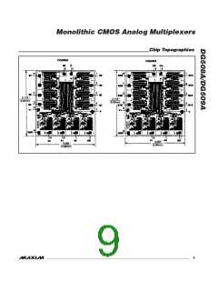
Monolithic CMOS Analog Multiplexers
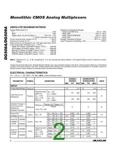
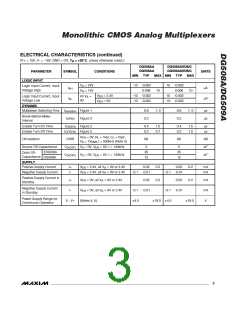
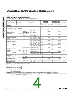
ELECTRICAL CHARACTERISTICS
(V+ = 15V, GND = 0V, T = T
to T , unless otherwise noted.)
MAX
A
MIN
DG508AA
DG509AA
DG508AD/E/B/C
DG509AD/E/B/C
PARAMETER
SWITCH
SYMBOL
CONDITIONS
UNITS
MIN TYP
MAX MIN TYP
MAX
Analog Signal Range
V
-15
+15
400
-15
+15
450
V
ANALOG
V
= 10V,
D
Sequence
each switch on,
I = -200µA
S
Drain-Source On-
Resistance
R
Ω
DS(ON)
S(OFF)
D(OFF)
V
V
= 0.8V,
= 2.4V
AL
V
= 10V,
D
400
+50
450
+50
AH
I = -200µA
S
V = 10V, V = -10V
S
D
Source Off-Leakage
Current
I
V
V
= 0V
nA
nA
EN
EN
V = -10V, V = -10V -50
-50
S
D
V
V
V
V
= 10V, V = -10V
+200
+200
+100
+100
D
D
D
D
S
DG508A
Drain Off-
= -10V, V = -10V -200
-200
-100
S
Leakage
I
= 0V
= 10V, V = -10V
S
Current
DG509A
= -10V, V = -10V -100
S
V
V
V
V
= V = 10V
+200
+100
+100
+100
S(all)
S(all)
S(all)
S(all)
D
Sequence each
switch on,
DG508A
Drain On-
Leakage
Current
= V = -10V
-200
-100
D
I
V
V
= 0.8V,
= 2.4V
nA
D(ON)
AL
= V = 10V
D
AH
DG509A
(Note 2)
= V = -10V
-100
-30
-100
-30
D
LOGIC INPUT
V
V
= 2.4V
= 15V
A
A
Logic Input Current,
Input Voltage High
I
µA
µA
AH
+30
+30
V
= 2.4V
= 0V
-30
-30
-30
-30
EN
EN
Logic Input Current,
Input Voltage Low
I
All V = 0V
A
AL
V
Note 2: I
is leakage from driver into on switch.
D(ON)
IV I
S
Note 3: Off-isolation = 20log
IV I
D
V
V
= input to off switch,
S
D
= output due to V .
S
Note 4: Electrical characteristics (such as on-resistance) change when power supplies other than 15V are used.
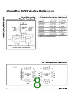
Note 5: For designs requiring single 5V or dual 5V operation, refer to Maxim’s improved MAX338 and MAX339. Minimum operating
voltage for DG508ADY and DG509ADY is 9V.
4
_______________________________________________________________________________________

 MAXIM [ MAXIM INTEGRATED PRODUCTS ]