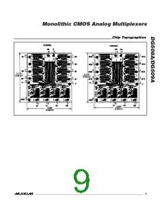
Monolithic CMOS Analog Multiplexers
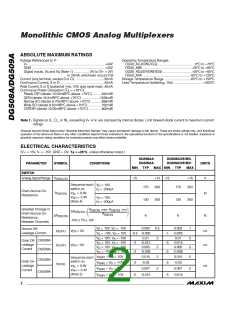
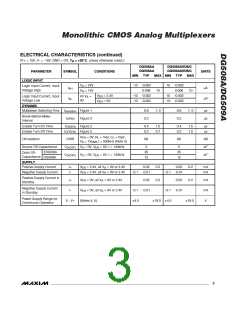
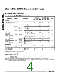
ELECTRICAL CHARACTERISTICS (continued)
(V+ = 15V, V- = -15V, GND = OV, T = +25°C, unless otherwise noted.)
A
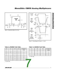
DG508AA
DG509AA
DG508AD/E/B/C
DG509AD/E/B/C
PARAMETER
LOGIC INPUT
SYMBOL
CONDITIONS
UNITS
MIN TYP
MAX MIN TYP
MAX
V
V
= 24V
= 15V
-10 -0.002
0.006
10 -0.002
0.006
A
A
Logic Input Current, Input
Voltage High
I
µA
µA
AH
10
10
V
V
= 2.4V
= 0V
-10 -0.002
-10 -0.002
10 -0.002
-10 -0.002
EN
EN
Logic Input Current, Input
Voltage Low
All V
0V
=
A
I
AL
DYNAMIC
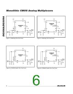
Multiplexer Switching Time
t
Figure 1
Figure 3
0.6
0.2
1. 0
0.6
0.2
1. 0
µs
µs
transition
Break-Before-Make
Interval
t
OPEN
Enable Turn-On Time
Enable Turn-Off Time
t
Figure 2
Figure 2
0.4
0.2
1.0
0.7
0.4
0.2
1.5
1.0
µs
µs
ON(EN)
t
OFF(EN)
V
= 0V, R = 1kΩ, C = l5pF,
L L
EN
Off-Isolation
OIRR
68
68
dB
pF
pF
V = 7V
f = 500kHz (Note 3)
S
RMS
Source Off-Capacitance
C
V = 0V, V = 0V, f = 140kHz
5
5
S(OFF)
D(OFF)
S
EN
IDG508A
DGS09A
25
12
25
12
Drain Off-
Capacitance
C
V = 0V, V = 0V, f = 140kHz
S
EN
SUPPLY
Positive Supply Current
Negative Supply Current
I+
I-
V
V
= 2.4V, all V = 0V or 2.4V
0.02
0.2
0.2
0.02
0.2
0.2
mA
mA
EN
EN
A
= 2.4V, all V = 0V or 2.4V
-0.1 -0.01
-0.1 -0.01
A
Positive Supply Current in
Standby
I+
I-
V
V
= 0V, all V = 0V or 2.4V
0.02
-0.1 -0.01
4.5
0.02
-0.1 -0.01
4.5
mA
mA
V
EN
EN
A
Negative Supply Current
in Standby
= 0V, all V = 0V or 2.4V
A
Power-Supply Range for
Continuous Operation
V-, V+
(Notes 4, 5)
18.0
18.0
_______________________________________________________________________________________
3

 MAXIM [ MAXIM INTEGRATED PRODUCTS ]