71M6543F/H and 71M6543G/GH Data Sheet
5.4.10 CE Calibration Parameters
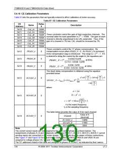
Table 87 lists the parameters that are typically entered to effect calibration of meter accuracy.
Table 87: CE Calibration Parameters
CE
Address
Defau
lt
Name
Description
CAL_IA
CAL_VA
CAL_IB
CAL_VB
CAL_IC
CAL_VC
CAL_ID
0x10
0x11
0x13
0x14
0x16
0x17
0x19
16384
16384
16384
16384
16384
16384
16384
These constants control the gain of their respective channels. The
nominal value for each parameter is 214 = 16384. The gain of each
channel is directly proportional to its CAL parameter. Thus, if the
gain of a channel is 1% low, CAL should be increased by 1%.
These constants control the CT phase compensation. No
compensation occurs when PHADJ_X = 0. As PHADJ_X is increased,
more compensation (lag) is introduced. The range is ± 215 – 1. If it
is desired to delay the current by the angle Φ, the equations are:
PHADJ_A
PHADJ_B
PHADJ_C
0x12
0x15
0x18
0
0
0
0.029615TANΦ
0.1714 − 0.0168⋅TANΦ
0.0206 ⋅TANΦ
PHADJ _ X = 220
at 60Hz
PHADJ _ X = 220
at 50Hz
0.1430 − 0.01226 ⋅TANΦ
The shunt delay compensation is obtained using the equation
provided below:
2πf
fs
2πf
fs
a2 cos2
+ 2abcos
+ b
DLYADJ_A
DLYADJ_B
0x12
0x15
0
0
2π
360
degrees 1+ 0.1∆degrees
214
(
)
DLYADJ _ X = ∆
2πf
csin
fs
where:
a = 2A
b = A2 +1
2휋푓
2
�
ꢁ
+ 2
푐 = 2퐴 + 4퐴푐표푠
푓
ꢀ
f is the mains frequency
fs is the sampling frequency
The table below provides the value of A for each channel:
Value of A
Channel
DLYADJ_C
0x18
0
(decimal)
DꢀYADJ_A
DLYADJ_B
DLYADJ_C
13840
11693
9359
Note:
The current sensor inputs are not assigned to the A, B and C phases in a fixed manner. The
assignments of phases A, B and C depends on how the IADC0-1, IADC2-3, IADC4-5, IADC6-7 current
sensing inputs are connected in the meter design. The CE code must be aware of these connections.
See Figure 31 and Figure 32 for typical meter configurations. VADC8, VADC9 and VADC10 are
assigned to voltage phases VA, VB and VC in a fixed manner, respectively.
The CE addresses listed in this table are assigned to phases A, B and C as indicated by their names.
130
© 2008–2011 Teridian Semiconductor Corporation
v1.2

 MAXIM [ MAXIM INTEGRATED PRODUCTS ]