DA6181B.002
5 May, 2011
TYPICAL APPLICATION (Continued)
Note 3: Power Down / Fast Startup Control
Both power down and fast startup is controlled using the PDN pin. The device is in power down (turned off) if
PDN1 = PDN2 = VDD and in power up with other three PDN1 and PDN2 control bit combinations (see table 1 on
page 4). Fast startup is triggered automatically when moving from power down to power up. The VDD must have
been high before moving from power down to power up to guarantee proper operation of fast startup circuitry.
Additionally the device should have been kept in power down state at least 50ms before power up. This
guarantees that the AGC capacitor voltage has been completely pulled to VDD during power down. The startup
time without proper fast startup control can be several minutes. With fast startup it is shortened typically to a few
seconds.
Note 4: Optional Control for AGC On/Hold
AON control pin has internal pull up which turns AGC circuit on all the time if AON pin is left unconnected.
Optionally AON control can be used to hold and release AGC circuit. Stepper motor drive of analog clock or
watch can produce disturbing amount of noise which can shift the input amplifier gain to non optimal level. This
can be avoided by controlling AGC hold (AON=VSS) during stepper motor drive periods and releasing AGC
(AON=VDD) when motors are not driven. The AGC should be in hold only during disturbances and kept on other
time released since due to leakage the AGC can still change slowly when in hold.
Note 5: Ferrite Antenna
The ferrite antenna converts the transmitted radio wave into a voltage signal. It has an important role in
determining receiver performance. Recommended antenna impedance at resonance is around 100 kΩ.
Low antenna impedance corresponds to low noise but often also to small signal amplitude. On the other hand
high antenna impedance corresponds to high noise but also large signal. The optimum performance where
signal-to-noise ratio is at maximum is achieved in between.
The antenna should have also some selectivity for rejecting near signal band disturbances. This is determined
by the antenna quality factor which should be approximately 100. Much higher quality factor antennas suffer from
extensive tuning accuracy requirements and possible tuning drifts by the temperature.
Antenna impedance Rant can be calculated using equation 1 where fres, L, Qant and C are resonance frequency
fres, coil inductance, antenna quality factor and antenna tuning capacitor respectively. Antenna quality factor Qant
is defined by ratio of resonance frequency fres and antenna bandwidth B (equation 2).
Qant
2π ⋅ fres ⋅C 2π ⋅ B ⋅C
1
Rant = 2π ⋅ fres ⋅ L ⋅Qant
=
=
Equation 1.
Equation 2.
fres
Qant
=
B
Table 4 below presents some antenna suppliers for time signal application.
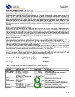
Table 4. Antenna Suppliers and Antenna Types in for Time Signal Application
Dimensions
Supplier
Antenna Type
Web Link
Micro Analog
Systems Oy
A10X60-77.5K222PY
A10X100-77.5K222PY
A3.5X4X15-7.87MH
A2X3X21-0.92MH
A3.75X3.75X23.6-0.92MH
60716 (60 kHz)
60708 (77.5 kHz)
ø 10 x 60 mm
ø 10 x 100 mm
3.5 x 4 x 15 mm
2 x 3 x 21 mm
3.75x3.75x23 mm
ø 10 x 60 mm
http://www.mas-
oy.com/en/products/radio-controlled-
clock-rcc/antennas/
HR Electronic
GmbH
http://www.hrelectronic.com/
Hitachi Metals AN-T702Sxx
AN-T702Mxx
AN-T702Lxx
19 x 5.5 x 6.3 mm http://www.hitachi-
28 x 5 x 5 mm
50 x 5 x 5 mm
75 x 15 x 6.3 mm
metals.co.jp/e/prod/prod06/p06_12.html
Premo
RCA-SMD-77A (77.5 kHz)
RCA-SMD-60A (60 kHz)
ACL80A (40 kHz)
http://www.grupopremo.com/
Sumida
ø 10 x 80 mm
www.sumida.co.jp/jeita/XJA021.pdf
8 (15)

 MAS [ MICRO ANALOG SYSTEMS ]