DA6181B.002
5 May, 2011
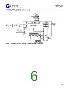
TYPICAL APPLICATION (Continued)
Note 1: Crystals
The crystals as well as ferrite antenna frequencies are chosen according to the time signal system (Table 2).
The reason why the crystal frequency is about 3 Hz higher than the signal frequency is that the crystal is
operated without the loading capacitor. Without loading capacitor the actual resonance frequency is about 3 Hz
lower than with load thus 77.503 kHz crystal resonates at 77.500 kHz when no loading capacitor is used.
Table 2. Time Signal System Frequencies
Location
Time Signal System
Antenna Frequency Recommended Crystal Frequency
DCF77
HBG
MSF
WWVB
JJY
BPC
Germany
Switzerland
United Kingdom
USA
Japan
China
77.5 kHz
75 kHz
60 kHz
60 kHz
40 kHz and 60 kHz
68.5 kHz
77.503 Hz
75.003 kHz
60.003 kHz
60.003 kHz
40.003 kHz and 60.003 kHz
68.505 kHz
The parasitic shunt capacitance C0 of the two crystals should be as similar to each other as possible since they
are used to cancel each other. Large shunt capacitance mismatch between the two crystals can lead to non-
ideal filter characteristics and wide noise band-width. Effectively this means lower sensitivity performance.
It should be noted that grounded crystal package has reduced shunt capacitance. This value is about 85% of
floating crystal shunt capacitance. For example crystal with 1pF floating package shunt capacitance can have
0.85pF grounded package shunt capacitance. PCB traces of crystal and external compensation capacitance
should be kept at minimum to minimize additional parasitic capacitance which can cause capacitance
mismatching.
When using MAS6181B1 it does not matter which of the two frequency crystals is connected to QO1 pin and
which to QO2 pin.
Table 3 below presents some crystal suppliers having suitable crystals for time signal receiver application.
Table 3. Crystal Suppliers and Crystal Types in Alphabetical Order for Time Signal Receiver Application
Dimensions
Supplier
Crystal Type
Web Link
Citizen
CFV-206
ø 2.0 x 6.0
ø 1.5 x 5.0
ø 2.0 x 6.0
ø 2.0 x 6.0
1.45 x 1.45 x 6.7
ø 1.2 x 4.7
http://www.citizen.co.jp/tokuhan/quartz/
http://www.epsontoyocom.co.jp/english/
Epson Toyocom C-2-Type
C-4-Type
KDS Daishinku
Microcrystal
Seiko
DT-261
MS3V-T1R
VTC-120
http://www.kds.info/index_en.htm
http://www.microcrystal.com/
http://www.sii-crystal.com
Instruments
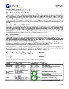
Note 2: AGC Capacitor
The 10µF AGC and 47nF DEC capacitors must have low leakage currents due to very small signal currents
through the capacitors. The insulation resistance of these capacitors should be at minimum several 100 MΩ.
Also probes with at least several 100 MΩ impedance should be used for voltage probing of the AGC and DEC
pins to not disturb their operation. Tantalum capacitors have lower leakage than the electrolyte capacitors. In
case of using electrolyte type AGC capacitor the capacitor voltage rating should be at least 25 V for sufficiently
low leakage. The DEC capacitor can be low leakage chip capacitor since its capacitance value is small.
It is recommended to connect both AGC and DEC capacitors to VDD (see application figures 1 and 2) although
VSS connection is also possible. The VDD connection provides better supply noise immunity because the
signals and AGC gain are referenced to VDD. Additionally leakage currents are minimized in this connection
because in power down the AGC pin voltage is pulled to VDD (to minimum AGC gain) providing zero voltage
over the AGC capacitor.
7 (15)

 MAS [ MICRO ANALOG SYSTEMS ]