DA6181B.002
5 May, 2011
FREQUENCY SELECTION
The power down control and frequency selection
using internal antenna’s tuning capacitor switch
(RFI2) are achieved by two digital control pins
PDN1 and PDN2. The control logic is presented in
table 1.
Table 1. Frequency selection and power down control
PDN1
PDN2
RFI2 Switch
Description
High
High
Open
Power down
High
Low
Low
Low
High
Low
Open
Closed
Closed
Antenna frequency 1
Antenna frequency 2, RFI2 capacitor connected in parallel with antenna
Antenna frequency 2, RFI2 capacitor connected in parallel with antenna
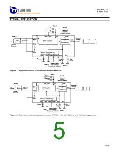
If frequency 1 is selected the RFI2 switch is open
(non conductive). Antenna frequency is determined
by antenna inductor LANT (see Typical Application on
page 5), antenna capacitor CANT1 and parasitic
capacitances related to antenna coil, inputs RFIP,
the lowest frequency of the two selected
frequencies.
It is recommended to switch the device to power
down for at least 50ms before switching to another
frequency. This guarantees fast startup in switching
to another frequency. During minimum 50ms power
down time the AGC capacitor voltage is completely
pulled to VDD to initialize proper startup conditions
for the AGC. Without the described proper fast
startup control the startup time can be several
minutes. With fast startup it is shortened typically to
a few seconds.
RFIM
and
RFI2
(see
Antenna
Tuning
Considerations below). Frequency 1 is the highest
frequency of the two selected frequencies.
If frequency 2 is selected then RFI2 switch is closed
to connect CANT2 to pin RFIM in parallel with ferrite
antenna and tune it to frequency 2. Frequency 2 is
ANTENNA TUNING CONSIDERATIONS
The ferrite bar antenna having inductance LANT and
parasitic coil capacitance CCOIL is tuned to two
reception frequencies f1 and f2 by parallel capacitors
CANT1 and CANT2. The receiver input stage and
resonance frequencies. COFF2 is switch capacitance
when switch is open. When the antenna switch is
closed the off capacitance is shorted by on
resistance of the switch and it is effectively
eliminated. Following relationships can be written
for the two tuning frequencies.
internal
antenna
capacitor
switches
capacitances CRFI and COFF2 which affect the
have
Frequency f1 (highest frequency):
CTOT1~CCOIL+CANT1+CRFI+COFF2, assuming CANT2>>COFF2
1
f1 =
2
π
LANT ⋅CTOT1
Frequency f2 (lowest frequency):
TOT2=CCOIL+CANT1+CANT2+CRFI
C
1
f2
=
2π LANT ⋅CTOT 2
4 (15)

 MAS [ MICRO ANALOG SYSTEMS ]