TYPICAL CHARACTERISTICS
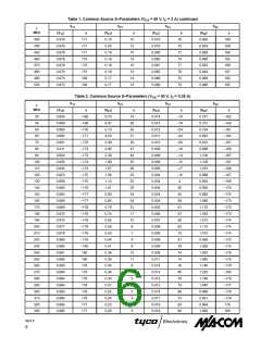
30
350
300
250
200
150
175 MHz
f = 150 MHz
200 MHz
25
20
15
10
5
V
DD
= 50 V
I
DQ
= 2 x 250 mA
V
I
DQ
= 50 V
= 2 x 250 mA
100
50
0
DD
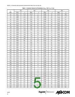
P
out
= 150 W
2
5
10
30
100
200
0
5
10
f, FREQUENCY (MHz)
P , INPUT POWER (WATTS)
in
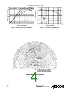
Figure 7. Output Power versus Input Power
Figure 8. Power Gain versus Frequency
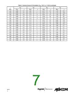
f = 175 MHz
150
125
INPUT, Z
(GATE TO GATE)
in
100
Z = 10 Ω
o
30
150
125
100
f = 175 MHz
OUTPUT, Z
(DRAIN TO DRAIN)
*
OL
30
Z * = Conjugate of the optimum load impedance
OL
Z * = into which the device output operates at a
OL
Z * = given output power, voltage and frequency.
OL
Figure 9. Input and Output Impedance
REV 9
4

 TE [ TE CONNECTIVITY ]