LT3840
operaTion
OVERVIEW
The externally compensated V voltage generates a
C
threshold for the differential current sense comparator.
During normal operation, the LT3840 internal oscillator
runs at the programmed frequency. At the beginning of
each oscillator cycle, the TG switch drive is turned on. The
TG switch drive stays enabled until the sensed inductor
TheLT3840providesasolutionforahighefficiency,general
purpose DC/DC converter. It is a wide input voltage range
switching regulator controller IC that uses a program-
mable fixed frequency, peak current mode architecture.
An internal switching regulator efficiently provides an
auxiliary bias supply to drive multiple, large N-channel
MOSFET switches.
current exceeds the V derived threshold of the current
C
sense comparator.
If the current comparator threshold is not reached for the
entire oscillator cycle, the switch driver stays on for up
to eight cycles. If after eight cycles the TG switch driver
is still on, it is turned off to regenerate the BOOST boot-
strapped supply.
The LT3840 includes functions such as average output
current control and monitoring, micro-power operation
with low output ripple, soft-start, output voltage tracking,
power good and a handful of protection features.
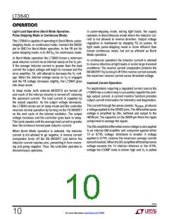
Voltage Control Loop
Whentheloadcurrentincreases, theFBvoltagedecreases
relative to the reference causing the EA to increase the V
C
The LT3840 uses peak current mode control to regulate
the supply output voltage. The error amplifier (EA) gener-
ates an error voltage (V ) based on the difference between
the feedback (FB) voltage and an internal reference.
voltageuntiltheaverageinductorcurrentmatchesthenew
load current. Refer to Figure 1 for a block diagram of the
LT3840 voltage control loop.
C
BOOST
TG
V
IN
INTV
CC
DRIVER
EXTERNAL
COMPONENTS
SW
ANTI SHOOT
THRU
V
OUT
INTV
CC
DRIVER
BG
BGRTN
Q
S
R
OSCILLATOR
SYNC
+
–
SENSE
+
–
RT
SENSE
FB
–
+
V
C
EA
V
REF
3840 BD
Figure 1. Peak Current Mode Voltage Control Functional Block Diagram
3840fa
For more information www.linear.com/LT3840
9

 Linear [ Linear ]