LT1584/LT1585/LT1587
U
W U U
APPLICATIONS INFORMATION
Overload Recovery
adjust pin capacitor should be 22µF. At 10kHz, only 0.22µF
is needed.
The LT1584 devices have safe-area protection similar to
the LT1083/LT1084/LT1085. The safe-area protection de-
creases current limit as input-to-output voltage increases.
This behavior keeps the power transistor inside a safe
operating region for all values of input-to-output voltage.
The LT1584 protection circuitry provides some output
current at all values of input-to-output voltage up to the 7V
maximum supply voltage. When power is first applied, the
inputvoltagerisesandtheoutputvoltagefollowstheinput.
The input-to-output voltage remains small and the regula-
tor can supply large output currents. This action permits
the regulator to start-up into very heavy loads.
Output Voltage
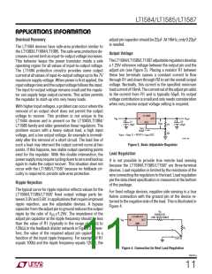
TheLT1584/LT1585/LT1587adjustableregulatorsdevelop
a 1.25V reference voltage between the output pin and the
adjust pin (see Figure 3). Placing a resistor R1 between
these two terminals causes a constant current to flow
through R1 and down through R2 to set the overall output
voltage. Normally, this current is the specified minimum
loadcurrentof10mA.Thecurrentoutoftheadjustpinadds
to the current from R1 and is typically 55µA. Its output
voltage contribution is small and only needs consideration
when very precise output voltage setting is required.
With higher input voltages, a problem can occur where the
removal of an output short does not permit the output
voltage to recover. This problem is not unique to the
LT1584 devices and is present on the LT1083/LT1084/
LT1085 family and older generation linear regulators. The
problem occurs with a heavy output load, a high input
voltage, and a low output voltage. An example is immedi-
ately after the removal of a short circuit. The load line of
such a load may intersect the output current curve at two
points. If this happens, two stable output operating points
exist for the regulator. With this double intersection, the
powersupplymayrequirecyclingdowntozeroandbackup
again to make the output recover. This situation does not
occur with the LT1585/LT1587 because no foldback cir-
cuitry is required to provide safe-area protection.
LT1584
V
IN
OUT
V
OUT
C2
22µF
IN
+
+
C1
10µF
ADJ
V
REF
R1
R2
I
ADJ
55µA
(1 + R2/R1) + I
ADJ
V
= V
REF
(R2)
OUT
LT1585 • F03
Figure 3. Basic Adjustable Regulator
Load Regulation
It is not possible to provide true remote load sensing
because the LT1584/LT1585/LT1587 are three-terminal
devices. Load regulation is limited by the resistance of the
wire connecting the regulators to the load. Load regulation
per the data sheet specification is measured at the bottom
of the package.
Ripple Rejection
The typical curve for ripple rejection reflects values for the
LT1584/LT1585/LT1587 fixed output voltage parts be-
tween 3.3V and 3.6V. In applications that require improved
ripple rejection, use the adjustable devices. A bypass
capacitor from the adjust pin to ground reduces the output
ripple by the ratio of VOUT/1.25V. The impedance of the
adjust pin capacitor at the ripple frequency should be less
than the value of R1 (typically in the range of 100Ω to
120Ω) in the feedback divider network in Figure 2. There-
fore, the value of the required adjust pin capacitor is a
function of the input ripple frequency. For example, if R1
equals 100Ω and the ripple frequency equals 120Hz, the
For fixed voltage devices, negative side sensing is a true
Kelvin connection with the ground pin of the device re-
turned to the negative side of the load. This is illustrated in
Figure 4.
R
P
PARASITIC
LINE RESISTANCE
LT1584-3.3
IN OUT
V
IN
GND
R
L
LT1585 • F04
Figure 4. Connection for Best Load Regulation
158457a
11

 Linear [ Linear ]