LT3592
APPLICATIONS INFORMATION
attheLT3592andtoforcethisveryhighfrequencyswitch-
ing current into a tight local loop, minimizing EMI. A 1μF
capacitor is capable of this task, but only if it is placed
close to the LT3592 and catch diode (see the PCB layout
section). Asecondprecautionregardingtheceramicinput
capacitor concerns the maximum input voltage rating of
theLT3592.Aceramicinputcapacitorcombinedwithtrace
or cable inductance forms a high quality (underdamped)
tank circuit. If the LT3592 circuit is plugged into a live
supply, the input voltage can ring to twice its nominal
value, possibly exceeding the LT3592’s voltage rating.
This situation can easily be avoided, as discussed in the
Hot Plugging Safety section. For more details, see Linear
Technology Application Note 88.
You can estimate output ripple with the following
equation:
ΔILP−P
8 • ƒ •COUT
VRIPPLE
=
where ΔI
is the peak-to-peak ripple current in the in-
LP-P
ductor. The RMS content of this ripple is very low, so the
RMS current rating of the output capacitor is usually not
a concern. It can be estimated with the formula:
ΔIL
IC(RMS)
=
12
The low ESR and small size of ceramic capacitors make
them the preferred type for LT3592 applications. Not all
ceramic capacitors are the same, though. Many of the
higher value ceramic capacitors use poor dielectrics with
high temperature and voltage coefficients. In particular,
Y5VandZ5Utypeslosealargefractionoftheircapacitance
with applied voltage and at temperature extremes.
Output Capacitor
For most 2.2MHz LED applications, a 3.3μF or higher
output capacitor is sufficient for stable operation. A
900kHz application should use a 4.7μF or higher output
capacitor. 400kHz applications require a 22μF or higher
output capacitor. The minimum recommended values
shouldprovideanacceptable(ifsomewhatunderdamped)
transient response, but larger values can always be used
when extra damping is required or desired.
Because loop stability and transient response depend on
the value of C , this loss may be unacceptable. Use X7R
OUT
and X5R types. Table 3 lists several capacitor vendors.
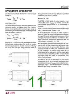
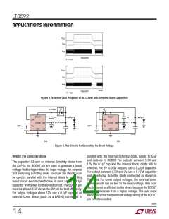
Figure 4 shows the transient response of the LT3592 when
switching between DIM and BRIGHT current levels with
twooutputcapacitorchoices.Theoutputloadistwoseries
Luxeon K2 Red LEDs, the DIM current is 50mA and the
BRIGHT current is 500mA, and the circuit is running at
900kHz. The upper photo shows the recommended 4.7μF
value. The second photo shows the improved response
resulting from a larger output capacitor.
Theoutputcapacitorfilterstheinductorcurrenttogenerate
an output with low voltage ripple. It also stores energy in
order to satisfy transient loads and stabilizes the LT3592’s
control loop. Because the LT3592 operates at a high fre-
quency,minimaloutputcapacitanceisnecessary.Inaddition,
the control loop operates well with or without the presence
of significant output capacitor equivalent series resistance
(ESR). Ceramic capacitors, which achieve very low output
ripple and small circuit size, are therefore an option.
Table 3. Capacitor Vendor Information
SUPPLIER
AVX
PHONE
FAX
WEBSITE
www.avxcorp.com
(803) 448-9411
(619) 661-6322
(408) 573-4150
(847) 803-6100
(803) 448-1943
(619) 661-1055
(408) 573-4159
(847) 803-6296
Sanyo
www.sanyovideo.com
Taiyo Yuden
TDK
www.t-yuden.com
www.component.tdk.com
3592fc
13

 Linear Systems [ Linear Systems ]