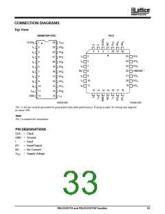
CONNECTION DIAGRAMS
Top View
SKINNYDIP/SOIC
PLCC
CLK/I
1
24
23
22
21
20
19
18
17
16
15
14
13
V
CC
0
1
2
3
4
5
6
7
8
9
I
I
2
I/O
I/O
I/O
I/O
I/O
I/O
I/O
I/O
I/O
I/O
I
9
8
7
6
5
4
3
2
1
0
4
3
2
1
28 27 26
3
I
I
I
5
25
24
23
22
21
20
19
I/O
I/O
I/O
I
4
3
4
5
7
6
5
6
I
5
7
I
6
NC
8
GND/NC *
I
7
I
I
I
9
I/O
I/O
I/O
I
8
6
7
8
4
3
2
10
11
I
9
I
10
11
12 13 14 15 16 17 18
I
10
GND 12
11
16564E-002
16564E-003
*For -5, this pin must be grounded for guaranteed data sheet performance. If not grounded, AC timing may degrade
by about 10%.
Note:
Pin 1 is marked for orientation.
PIN DESIGNATIONS
CLK = Clock
GND = Ground
I
= Input
I/O
NC
= Input/Output
= No Connect
= Supply Voltage
V
CC
PALCE22V10 and PALCE22V10Z Families
33

 LATTICE [ LATTICE SEMICONDUCTOR ]