POWER-UP RESET
The power-up reset feature ensures that all flip-flops will be reset to LOW after the device has been
powered up. The output state will depend on the programmed pattern. This feature is valuable in
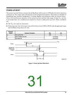
simplifying state machine initialization. A timing diagram and parameter table are shown below.
Due to the synchronous operation of the power-up reset and the wide range of ways VCC can rise
to its steady state, two conditions are required to ensure a valid power-up reset. These conditions
are:
The VCC rise must be monotonic.
Following reset, the clock input must not be driven from LOW to HIGH until all applicable input
and feedback setup times are met.
Parameter
Symbol
Parameter Description
Max
Unit
t
Power-up Reset Time
1000
ns
PR
t
Input or Feedback Setup Time
Clock Width LOW
See Switching
Characteristics
S
t
WL
V
CC
4 V
V
Off
CC
Power
t
PR
Registered
Active-Low
Output
t
S
Clock
t
WL
16564E-021
Figure 3. Pow er-Up Reset Waveform
PALCE22V10 and PALCE22V10Z Families
31

 LATTICE [ LATTICE SEMICONDUCTOR ]