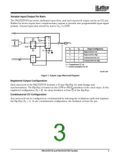
Variable Input/Output Pin Ratio
The PALCE22V10 has twelve dedicated input lines, and each macrocell output can be an I/O pin.
Buffers for device inputs have complementary outputs to provide user-programmable input signal
polarity. Unused input pins should be tied to VCC or GND.
1
1
0
0
0
1
0
1
AR
I/O
D Q
Q
n
CLK
S
S
Output Configuration
Registered/Active Low
1
0
S
SP
1
0
0
S
0
0
1
1
1
0
1
Registered/Active High
0
1
Combinatorial/Active Low
Combinatorial/Active High
0 = Programmed EE bit
1 = Erased (charged) EE bit
16564E-004
Figure 1. Output Logic Macrocell Diagram
Registered Output Configuration
Each macrocell of the PALCE22V10 includes a D-type flip-flop for data storage and
synchronization. The flip-flop is loaded on the LOW-to-HIGH transition of the clock input. In the
registered configuration (S1 = 0), the array feedback is from Q of the flip-flop.
Combinatorial I/O Configuration
Any macrocell can be configured as combinatorial by selecting the multiplexer path that bypasses
the flip-flop (S1 = 1). In the combinatorial configuration, the feedback is from the pin.
PALCE22V10 and PALCE22V10Z Families
3

 LATTICE [ LATTICE SEMICONDUCTOR ]