IRS20124S(PbF)
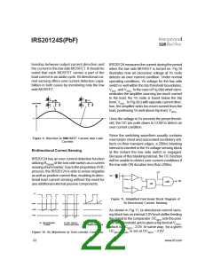
tionship between output current direction and
the current in the low side MOSFET. It should be
noted that each MOSFET carries a part of the
load current in an audio cycle. Bi-directional cur-
rent sensing offers over current detection capa-
bilities in both cases by monitoring only the low
side MOSFET.
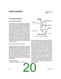
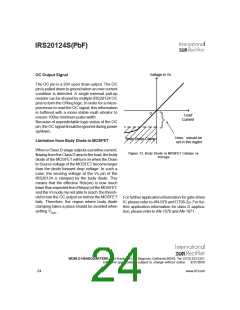
IRS20124 measures the current during the period
when the low side MOSFET is turned on. Fig.10
illustrates how an excessive voltage at Vs node
detects an over current condition. Under normal
operating conditions, Vs voltage for the low side
switch is well within the trip threshold boundaries,
VSOC- and VSOC+. In the case of Fig.9(b) which dem-
onstrates the amplifier sourcing too much current
to the load, the Vs node is found below the trip
level, VSOC-. In Fig.9(c) with opposite current direc-
tion, the amplifier sinks too much current from the
load, positioning Vs well above trip level, VSOC+.
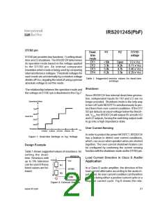
Load Current
0
Once the voltage in Vs exceeds the preset thresh-
old, the OC pin pulls down to COM to detect an
over current condition.
Since the switching waveform usually contains
over/under shoot and associated oscillatory arti-
facts on their transient edges, a 200ns blanking
interval is inserted in the Vs voltage sensing block
at the instant the low side switch is engaged.
Because of this blanking interval, the OC function
will be unable to detect over current conditions if
the low side ON duration less than 200ns.
Figure 9. Direction in MMOSFET Current and Load
Current
Bi-directional Current Sensing
IRS20124 has an over current detection function
utilizing RDS(ON) of the low side switch as a current
sensing shunt resistor. Due to the proprietary HVIC
process, the IRS20124 is able to sense negative
as well as positive current flow, enabling bi-direc-
tional load current sensing without the need for
any additional external passive components.
LO
Vs
+
-
OCSET1
OC
AND
OR
OCSET2
+
-
vs
~
~
~
~
~
~
~
~
~
~
~
~
~
~
~
~
~
~
~
~
~
~
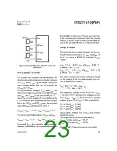
Figure 11. Simplified Functional Block Diagram of
Bi-Directional Current Sensing
Vsoc+
COM
Vsoc-
As shown in Fig.11, bi-directional current sens-
ing block has an internal 2.0V level shifter feeding
the signal to the comparator. OC
sets the posi-
tive side threshold, and is given aStEriTp1 level at VSOC+
,
(a) Normal Operation
Condition
(b) Over- Current in
Positive Load Current
(c) Over- Current in
Negative Load Current
which is OCSET1 - 2.0V. In same way, for a given
OCSET2, VSOC- is set at OCSET2 – 2.0V
Figure 10. Vs Waveform in Over-current Condition
22
www.irf.com

 INFINEON [ Infineon ]