IRS20124S(PbF)
Functional description
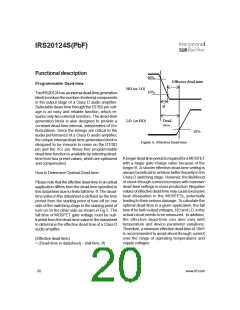
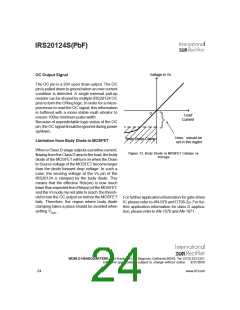
90%
10%
Effective dead-time
Programmable Dead-time
HO (or LO)
LO (or HO)
The IRS20124 has an internal dead-time generation
block to reduce the number of external components
in the output stage of a Class D audio amplifier.
Selectable dead-time through the DT/SD pin volt-
age is an easy and reliable function, which re-
quires only two external resistors. The dead-time
generation block is also designed to provide a
constant dead-time interval, independent of Vcc
fluctuations. Since the timings are critical to the
audio performance of a Class D audio amplifier,
the unique internal dead-time generation block is
designed to be immune to noise on the DT/SD
pin and the Vcc pin. Noise-free programmable
dead-time function is available by selecting dead-
time from four preset values, which are optimized
and compensated.
tf
Dead-
10%
Figure 6. Effective Dead-time
A longer dead time period is required for a MOSFET
with a larger gate charge value because of the
longer tf. A shorter effective dead-time setting is
always beneficial to achieve better linearity in the
Class D switching stage. However, the likelihood
of shoot-through current increases with narrower
dead-time settings in mass production. Negative
values of effective dead-time may cause excessive
heat dissipation in the MOSFETs, potentially
leading to their serious damage. To calculate the
optimal dead-time in a given application, the fall
time tf for both output voltages, HO and LO, in the
actual circuit needs to be measured. In addition,
the effective dead-time can also vary with
temperature and device parameter variations.
Therefore, a minimum effective dead-time of 10nS
is recommended to avoid shoot-through current
over the range of operating temperatures and
supply voltages.
How to Determine Optimal Dead-time
Please note that the effective dead-time in an actual
application differs from the dead-time specified in
this datasheet due to finite fall time, tf. The dead-
time value in this datasheet is defined as the time
period from the starting point of turn-off on one
side of the switching stage to the starting point of
turn-on on the other side as shown in Fig.5. The
fall time of MOSFET gate voltage must be sub-
tracted from the dead-time value in the datasheet
to determine the effective dead time of a Class D
audio amplifier.
(Effective dead-time)
= (Dead-time in datasheet) – (fall time, tf)
20
www.irf.com

 INFINEON [ Infineon ]