IRL7486MTRPbF
10
1
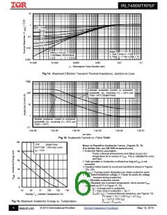
D = 0.50
0.20
0.10
0.05
0.1
0.02
0.01
0.01
Notes:
1. Duty Factor D = t1/t2
2. Peak Tj = P dm x Zthjc + Tc
SINGLE PULSE
( THERMAL RESPONSE )
0.001
1E-006
1E-005
0.0001
0.001
0.01
0.1
t
, Rectangular Pulse Duration (sec)
1
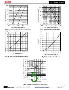
Fig 14. Maximum Effective Transient Thermal Impedance, Junction-to-Case
1000
100
10
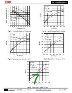
Allowed avalanche Current vs avalanche
pulsewidth, tav, assuming Tj = 125°C and
Tstart =25°C (Single Pulse)
1
Allowed avalanche Current vs avalanche
pulsewidth, tav, assuming j = 25°C and
Tstart = 125°C.
0.1
1.0E-06
1.0E-05
1.0E-04
1.0E-03
1.0E-02
1.0E-01
tav (sec)
Fig 15. Avalanche Current vs. Pulse Width
100
80
60
40
20
0
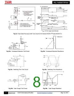
TOP
Single Pulse
Notes on Repetitive Avalanche Curves , Figures 15, 16:
(For further info, see AN-1005 at www.irf.com)
1.Avalanche failures assumption:
BOTTOM 1.0% Duty Cycle
I
= 123A
D
Purely a thermal phenomenon and failure occurs at a
temperature far in excess of Tjmax. This is validated for every
part type.
2. Safe operation in Avalanche is allowed as long asTjmax is not
exceeded.
3. Equation below based on circuit and waveforms shown in Figures
23a, 23b.
4. PD (ave) = Average power dissipation per single avalanche pulse.
5. BV = Rated breakdown voltage (1.3 factor accounts for voltage
increase during avalanche).
6. Iav = Allowable avalanche current.
7. T = Allowable rise in junction temperature, not to exceed Tjmax
(assumed as 25°C in Figure 14, 15).
tav = Average time in avalanche.
D = Duty cycle in avalanche = tav ·f
25
50
75
100
125
150
ZthJC(D, tav) = Transient thermal resistance, see Figures 13)
Starting T , Junction Temperature (°C)
J
PD (ave) = 1/2 ( 1.3·BV·Iav) = T/ ZthJC
I
av = 2T/ [1.3·BV·Zth]
Fig 16. Maximum Avalanche Energy vs. Temperature
EAS (AR) = PD (ave)· av
t
6
www.irf.com
© 2015 International Rectifier
Submit Datasheet Feedback
May 14, 2015

 INFINEON [ Infineon ]