IRL7486MTRPbF
Absolute Maximum Ratings
Symbol
ID @ TC = 25°C Continuous Drain Current, VGS @ 10V (Silicon Limited)
ID @ TC = 100°C Continuous Drain Current, VGS @ 10V (Silicon Limited)
Parameter
Max.
209
132
836
Units
A
Pulsed Drain Current
Maximum Power Dissipation
Linear Derating Factor
IDM
104
PD @TC = 25°C
W
W/°C
V
0.83
Gate-to-Source Voltage
Operating Junction and
Storage Temperature Range
± 20
VGS
TJ
TSTG
-55 to + 150
°C
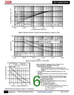
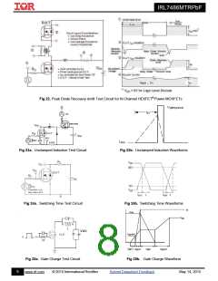
Avalanche Characteristics
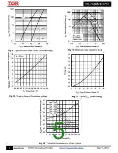
EAS (Thermally limited) Single Pulse Avalanche Energy
80
mJ
Single Pulse Avalanche Energy
Single Pulse Avalanche Energy Tested Value
Avalanche Current
EAS (Thermally limited)
EAS (tested)
IAR
190
111
A
See Fig.15,16, 23a, 23b
EAR
Repetitive Aval`anche Energy
mJ
Thermal Resistance
Symbol
Parameter
Typ.
–––
12.5
20
Max.
60
Units
Junction-to-Ambient
RJA
Junction-to-Ambient
Junction-to-Ambient
Junction-to-Case
Junction-to-PCB Mounted
–––
–––
1.2
RJA
°C/W
RJA
RJC
–––
0.75
–––
RJ-PCB
Static @ TJ = 25°C (unless otherwise specified)
Symbol
V(BR)DSS
Parameter
Min. Typ. Max. Units
Conditions
VGS = 0V, ID = 250µA
Drain-to-Source Breakdown Voltage
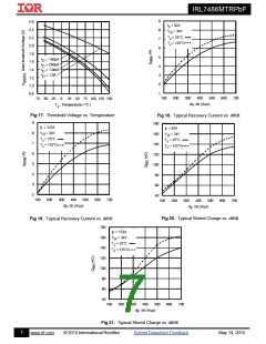
Breakdown Voltage Temp. Coefficient
Static Drain-to-Source On-Resistance
40
––– –––
V
–––
35 ––– mV/°C Reference to 25°C, ID = 1.0mA
V(BR)DSS/TJ
RDS(on)
––– 1.0 1.25
––– 1.5 2.0
1.0 1.8 2.5
VGS = 10V, ID = 123A
m
V
GS = 4.5V, ID = 62A
VDS = VGS, ID = 150µA
VGS(th)
IDSS
Gate Threshold Voltage
V
––– ––– 1.0
––– ––– 150
––– ––– 100
––– ––– -100
––– 0.97 –––
V
DS = 40V, VGS = 0V
Drain-to-Source Leakage Current
µA
V
DS = 40V, VGS = 0V, TJ = 125°C
IGSS
Gate-to-Source Forward Leakage
Gate-to-Source Reverse Leakage
Internal Gate Resistance
VGS = 20V
GS = -20V
nA
V
RG
Notes:
Mounted on minimum footprint full size board with metalized
back and with small clip heatsink.
TC measured with thermocouple mounted to top (Drain) of part.
Used double sided cooling , mounting pad with large heatsink.
Mounted to a PCB with small clip
heatsink (still air)
Mounted on minimum footprint full size
board with metalized back and with
small clip heatsink (still air)
Surface mounted on 1 in. square Cu
board (still air).
2
www.irf.com
© 2015 International Rectifier
Submit Datasheet Feedback
May 14, 2015

 INFINEON [ Infineon ]