Adjustments of DC offset and Switching Frequency
Component Number
Adjustment
R10
R26
R22
R27
DC offset for CH-1
Switching Frequency for CH-1
DC offset for CH-2
Switching Frequency for CH-2
Adjustments have to be done at an idling condition with no signal input.
Note: The PWM switching frequency in this type of self oscillating scheme greatly impacts the audio
performances, especially in the case where two or more channels are in close proximity.
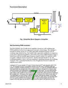
Thermal Considerations
The IRAUDAMP1 unitlizes a relatively thick aluminum block heatsink for peak power output handling
capabilities. It can handle continuous 1/8 of the rated power, which is generally considered to be a
normal operating condition in safety standards, for a considerable length of time such as one hour. The
size of the heatsink, however, is not sufficient to handle continuous rated power.
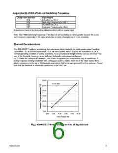
Fig.2 shows the relationship between total power dissipation and temperature rise at equilibrium. If
testing requires running conditions with continuous power a higher than 1/8 of the rated power, then,
attach extensions to the top of the heatsink using three M4 screw taps prepared for this purpose. Please
note that the heatsink is electrically connected to the GND pin.
60.00
Ta=25 degC
50.00
40.00
30.00
20.00
10.00
0.00
0.00
2.00
4.00
6.00
8.00
10.00
Total Power (W)
Fig.2 Heatsink Thermal Characteristic at Equilibrium
www.irf.com
5

 INFINEON [ Infineon ]