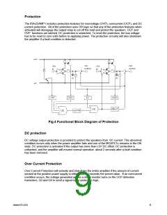
Under normal conditions the SD signal is low and the drive signal are passed directly through the
AND gates to the IR2011S gate driver.
The IR2011 drives two IRFB23N15D MOSFETs in the power stage to provide the amplified
Digital PWM waveform.
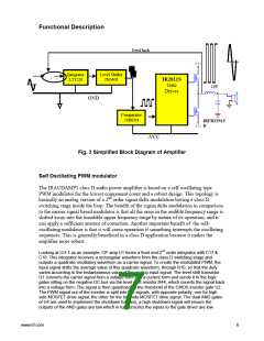
The amplified analog output is recreated by demodulating the amplified PWM . This is done by
means of the LC Low Pass Filter formed by L1 and C51, which filters out the class D switching
signal .
Switching Frequency
The self oscillating frequency is determined by the total delay time inside the loop. The following
parameters affect the frequency.
-
-
-
-
Delay time in logic circuits
The gate driver propagation delay
MOSFET switching speed
Integration time constant in the front end integrator, e.g. R1, R23, R26, C17, and C18 for
CH-1.
-
Supply Voltages
Gate Driver
The IRAUDAMP1 uses the IR2011S gate driver IC which is suitable for high speed, high speed
switching applications up to 200V. In this design, the difference between ton and toff is used to
generate a dead-time (a blanking time in between the on state of the two MOSFETs). Because of
this, there is no gate timing adjustment on the board.
MOSFET Gate Resistor
In order to add a little more dead-time and compensate for the finite switching transient time in
the MOSFET, a schottky diode is added in parallel with the gate resistor. The gate resistor (R31
and R50 in CH-1) adds about 10nS of delay time at turn on by limiting the gate charging current
to the IRFB23N15D. The schottky diode bypasses the gate resistor in the gate discharge path,
so that there is no falling edge delay. The delay at the rising edge adds dead time.
Startup Circuit
A self oscillating scheme contains class D switching stage that requires a start-up triggering
signal to charge the high side bootstrap capacitor . The starter circuits, Q9 and Q10, detect the
rising edge of –Vcc and turn the low side MOSFETs on for about 200mS to charge the bootstrap
capacitors C23 and C24, then release the loop allowing the oscillation to start.
Housekeeping Voltage Regulators
The IRAUDAMP1 contains following regulators to accommodate all the necessary functions on
the board.
Regulator
+5V
Component #
Q18
Usage
OP Amps in the modulator
OP Amps in the modulator, Startup circuit
Logic ICs
-5V
Q17
-Vcc+5V
-Vcc+12V
U13, U14
U11
Gate driver IC, Protection circuits
www.irf.com
7

 INFINEON [ Infineon ]