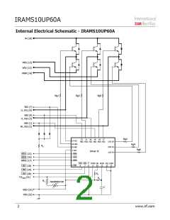
IRAMS10UP60A
Inverter Section Electrical Characteristics @ TJ = 25°C
Symbol
Parameter
Min
Typ
Max
Units Conditions
Collector-to-Emitter Breakdown
Voltage
V(BR)CES
600
---
---
V
V/°C
V
VIN=0V, IC=20µA
Temperature Coeff. Of
Breakdown Voltage
VIN=0V, IC=1.0mA
(25°C - 150°C)
∆V(BR)CES / ∆T
VCE(ON)
---
0.57
---
---
---
---
---
1.7
2.0
5
2.0
2.4
15
IC=5A TJ=25°C, VDD=15V
IC=5A TJ=150°C
VIN=5V, V+=600V
VIN=5V, V+=600V, TJ=150°C
Collector-to-Emitter Saturation
Voltage
Zero Gate Voltage Collector
Current-to-Emitter
ICES
µA
10
40
Zero Gate Phase-to-Phase
Current
Ilk_module
VFM
--
--
50
µA
VIN=5V, V+=600V
---
---
1.8
1.3
2.35
1.7
IC=5A
Diode Forward Voltage Drop
V
IC=5A, TJ=150°C
Inverter Section Switching Characteristics
Conditions
IC=5A, V+=400V
VDD=15V, L=1mH
Symbol
Parameter
Min
---
---
---
---
---
---
Typ
200
75
Max
235
100
335
360
165
525
Units
Eon
Turn-On Switching Loss
Turn-Off Switching Loss
Total Switching Loss
Turn-on Swtiching Loss
Turn-off Switching Loss
Total Switching Loss
Eoff
µJ
Etot
275
300
135
435
TJ=25°C
TJ=150°C
See CT1
Eon
Eoff
µJ
Energy losses include "tail" and
diode reverse recovery
Etot
Diode Reverse Recovery
energy
Erec
trr
---
---
30
40
µJ
TJ=150°C, V+ =400V VDD=15V,
IF=5A, L=1mH
Diode Reverse Recovery time
100
145
ns
TJ=150°C, IC=5A, VP=600V
V+=480V, VDD=+15V to 0V
See CT3
Reverse Bias Safe Operating
Area
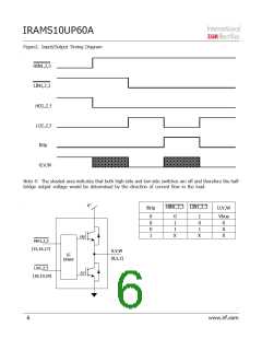
FULL SQUARE
---
RBSOA
SCSOA
TJ=150°C, VP=600V,
V+=360V,
Short Circuit Safe Operating
Area
10
---
µs
VDD=+15V to 0V
See CT2
Thermal Resistance
Symbol
Parameter
Min
Typ
Max
Units Conditions
Junction to case thermal
resistance, each IGBT under
inverter operation.
Rth(J-C)
---
4.2
4.7
°C/W
Flat, greased surface.
Heatsink compound thermal
conductivity - 1W/mK
Junction to case thermal
resistance, each Diode under
inverter operation.
Rth(J-C)
---
---
5.5
0.1
6.5
---
°C/W
°C/W
Thermal Resistance case to
sink
Rth(C-S)
www.irf.com
3

 INFINEON [ Infineon ]