IRAMS10UP60A
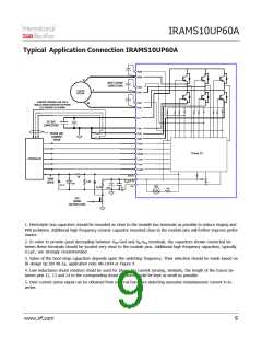
Typical Application Connection IRAMS10UP60A
VBW
VSW
U
BOOT-STRAP
CAPACITORS
VBV
VSV
V
3-ph AC
MOTOR
CURRENT SENSING CAN USE A
SINGLE SENSE RESISTOR OR PHASE
LEG SENSING AS SHOWN
VBU
VSU
W
V+
DC BUS
CAPACITORS
LeU
LeV
PHASE LEG
CURRENT
SENSE
LeW
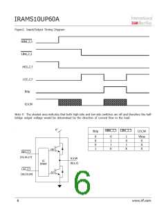
HINU
HINV
HINW
LINU
LINV
LINW
Driver IC
CONTROLLER
T/ITRIP
VDD(15 V)
VSS
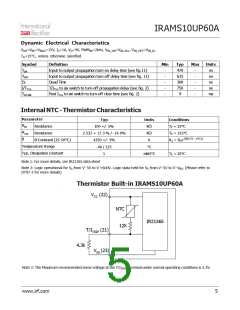
5k
TEMP
SENSE
6.8K
1m
3.3 V
NTC
10.2k
0.1
m
10m
12k
O/C
SENSE
(ACTIVE LOW)
1. Electrolytic bus capacitors should be mounted as close to the module bus terminals as possible to reduce ringing and
EMI problems. Additional high frequency ceramic capacitor mounted close to the module pins will further improve perfor-
mance.
2. In order to provide good decoupling between VCC-Gnd and VB-VSS terminals, the capacitors shown connected be-
tween these terminals should be located very close to the module pins. Additional high frequency capacitors, typically
0.1µF, are strongly recommended.
3. Value of the boot-strap capacitors depends upon the switching frequency. Their selection should be made based on
IR design tip DN 98-2a, application note AN-1044 or Figure 9.
4. Low inductance shunt resistors shuld be used for phase leg current sensing. Similarly, the length of the traces be-
tween pins 12, 13 and 14 to the corrisponding shunt resistors should be kept as small as possible.
5. Over-current sense signal can be obtained from external hardware detecting excessive instantaneous current in in-
verter.
www.irf.com
9

 INFINEON [ Infineon ]