X9C102, X9C103, X9C104, X9C503
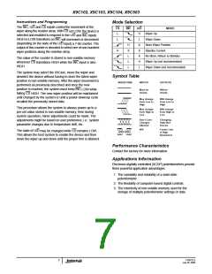
Mode Selection
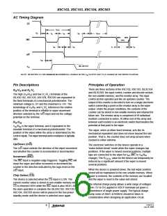
Instructions and Programming
The INC, U/D and CS inputs control the movement of the
wiper along the resistor array. With CS set LOW, the device is
selected and enabled to respond to the U/D and INC inputs.
HIGH to LOW transitions on INC will increment or decrement
(depending on the state of the U/D input) a 7-bit counter. The
output of this counter is decoded to select one of one-hundred
wiper positions along the resistive array.
CS
INC
U/D
MODE
L
H
Wiper Up
L
L
Wiper Down
H
X
Store Wiper Position
H
X
L
X
X
Standby Current
No Store, Return to Standby
The value of the counter is stored in non-volatile memory
whenever CS transitions HIGH while the INC input is also
HIGH.
L
L
H
L
Wiper Up (not recommended)
Wiper Down (not recommended)
The system may select the X9Cxxx, move the wiper and
deselect the device without having to store the latest wiper
position in non-volatile memory. After the wiper movement is
performed as previously described and once the new
position is reached, the system must keep INC LOW while
taking CS HIGH. The new wiper position will be maintained
until changed by the system or until a power-down/up cycle
recalled the previously stored data.
Symbol Table
WAVEFORM
INPUTS
OUTPUTS
Must be
steady
Will be
steady
May change
from Low to
High
Will change
from Low to
High
This procedure allows the system to always power-up to a
pre-set value stored in non-volatile memory; then during
system operation, minor adjustments could be made. The
adjustments might be based on user preference, i.e.: system
parameter changes due to temperature drift, etc.
May change
from High to
Low
Will change
from High to
Low
Don’t Care:
Changes
Allowed
Changing:
State Not
Known
N/A
Center Line
is High
Impedance
The state of U/D may be changed while CS remains LOW.
This allows the host system to enable the device and then
move the wiper up and down until the proper trim is attained.
Performance Characteristics
Contact the factory for more information.
Applications Information
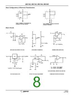
Electronic digitally controlled (XCDP) potentiometers provide
three powerful application advantages:
1. The variability and reliability of a solid-state
potentiometer.
2. The flexibility of computer-based digital controls.
3. The retentivity of non-volatile memory used for the
storage of multiple potentiometer settings or data.
FN8222.3
July 20, 2009
7

 INTERSIL [ Intersil ]