X9C102, X9C103, X9C104, X9C503
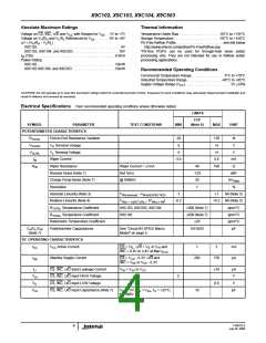
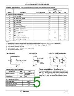
Electrical Specifications Over recommended operating conditions unless otherwise stated. (Continued)
LIMITS
TYP
SYMBOL
PARAMETER
TEST CONDITIONS
MIN
(Note 6)
MAX
UNIT
AC OPERATION CHARACTERISTICS
tCl
tlD
CS to INC Setup
100
100
2.9
1
ns
ns
INC HIGH to U/D Change
U/D to INC Setup
tDI
µs
tlL
INC LOW Period
µs
tlH
INC HIGH Period
1
µs
tlC
INC Inactive to CS Inactive
CS Deselect Time (STORE)
CS Deselect Time (NO STORE)
INC to VW/RW Change
INC Cycle Time
1
µs
tCPH
tCPH
20
100
ms
ns
(5)
tIW
100
500
µs
tCYC
tCYC
tR, tF
tPU
2
µs
INC Input Rise and Fall Time
Power-up to Wiper Stable (Note 7)
500
50
µs
µs
V
CC Power-up Rate (Note 7)
0.2
V/ms
NOTES:
3. Absolute linearity is utilized to determine actual wiper voltage vs expected voltage = [VW(n)(actual) - VW(n)(expected )] = ±1 MI Maximum.
4. Relative linearity is a measure of the error in step size between taps = VW(n + 1) - [VW(n) + MI] = +0.2 MI.
5. 1 MI = Minimum Increment = RTOT/99.
6. Typical values are for TA = +25°C and nominal supply voltage.
7. This parameter is not 100% tested.
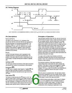
Test Circuit #1
Test Circuit #2
Circuit #3 SPICE Macro Model
V /R
V /R
R
H
H
H
R
TOTAL
R
R
H
L
TEST POINT
C
L
C
C
W
L
V
10pF
S
TEST POINT
V /R
V
/R
w
W
w
W
FORCE
CURRENT
10pF
25pF
V /R
L
V /R
L
L
L
R
W
Power-up and Down Requirements
Endurance and Data Retention
At all times, voltages on the potentiometer pins must be less
than ±VCC. The recall of the wiper position from non-volatile
memory is not in effect until the VCC supply reaches its final
value. The VCC ramp rate specification is always in effect.
PARAMETER
MIN
UNIT
Medium Endurance
100,000
Data changes per bit
per register
Data Retention
100
years
AC Conditions of Test
Input Pulse Levels
0V to 3V
10ns
Input Rise and Fall Times
Input Reference Levels
1.5V
FN8222.3
July 20, 2009
5

 INTERSIL [ Intersil ]