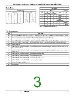
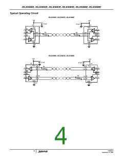
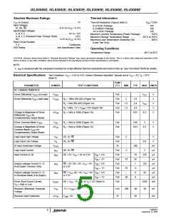
ISL83080E, ISL83082E, ISL83083E, ISL83085E, ISL83086E, ISL83088E
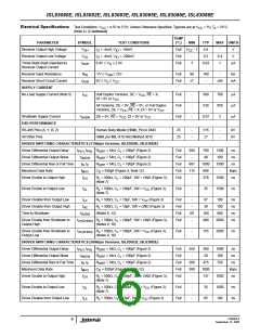
Electrical Specifications Test Conditions: V = 4.5V to 5.5V; Unless Otherwise Specified. Typicals are at V
= 5V, T = 25°C
A
CC
CC
(Note 4) (Continued)
TEMP
PARAMETER
Driver Disable from Output High
Time to Shutdown
SYMBOL
TEST CONDITIONS
= 500Ω, C = 15pF, SW = GND (Figure 3)
(°C)
Full
Full
Full
MIN
TYP
MAX UNITS
t
R
-
60
-
38
100
600
ns
ns
ns
HZ
L
L
t
(Notes 9, 12)
160
260
SHDN
Driver Enable from Shutdown to
Output High
t
R
= 500Ω, C = 100pF, SW = GND (Figure 3),
1500
ZH(SHDN)
L
L
(Notes 9, 10)
= 500Ω, C = 100pF, SW = V (Figure 3),
CC
Driver Enable from Shutdown to
Output Low
t
R
Full
-
155
1500
ns
ZL(SHDN)
L
L
(Notes 9, 10)
DRIVER SWITCHING CHARACTERISTICS (10Mbps Versions; ISL83086E, ISL83088E)
Driver Differential Output Delay
Driver Differential Output Skew
Driver Differential Rise or Fall Time
Maximum Data Rate
t
t
R
R
R
C
R
= 54Ω, C = 100pF (Figure 2)
Full
Full
Full
Full
Full
-
-
20
1
60
10
25
-
ns
ns
PLH, PHL
DIFF
DIFF
DIFF
L
t
= 54Ω, C = 100pF (Figure 2)
SKEW
L
t , t
= 54Ω, C = 100pF (Figure 2)
-
13
15
35
ns
R
F
L
f
= 470pF (Figure 4, Note 12)
10
-
Mbps
ns
MAX
D
L
Driver Enable to Output High
t
= 500Ω, C = 100pF, SW = GND (Figure 3),
150
ZH
L
(Note 7)
= 500Ω, C = 100pF, SW = V (Figure 3),
CC
Driver Enable to Output Low
t
R
Full
-
30
150
ns
ZL
L
L
(Note 7)
Driver Disable from Output Low
Driver Disable from Output High
Time to Shutdown
t
R
R
= 500Ω, C = 15pF, SW = V
(Figure 3)
Full
Full
Full
Full
-
-
66
38
100
100
600
250
ns
ns
ns
ns
LZ
L
L
CC
t
= 500Ω, C = 15pF, SW = GND (Figure 3)
HZ
L
L
t
(Notes 9, 12)
R = 500Ω, C = 100pF, SW = GND (Figure 3),
L
60
-
160
115
SHDN
Driver Enable from Shutdown to
Output High
t
ZH(SHDN)
L
(Notes 9, 10)
= 500Ω, C = 100pF, SW = V (Figure 3),
CC
Driver Enable from Shutdown to
Output Low
t
R
Full
-
84
250
ns
ZL(SHDN)
L
L
(Notes 9, 10)
RECEIVER SWITCHING CHARACTERISTICS (115kbps and 500kbps Versions; ISL83080E-ISL83085E)
Maximum Data Rate
f
(Figure 5, Note 12)
(Figure 5)
Full
Full
Full
Full
0.5
10
100
7
-
Mbps
ns
MAX
Receiver Input to Output Delay
t
, t
-
-
-
150
10
PLH PHL
Receiver Skew | t
- t
PLH PHL
|
t
(Figure 5)
ns
SKD
Receiver Enable to Output Low
t
R
= 1kΩ, C = 15pF, SW = V (Figure 6),
CC
10
50
ns
ZL
L
L
(Note 8)
Receiver Enable to Output High
t
t
R
= 1kΩ, C = 15pF, SW = GND (Figure 6),
Full
-
10
50
ns
ZH
L
L
(Note 8)
Receiver Disable from Output Low
Receiver Disable from Output High
Time to Shutdown
t
R
R
= 1kΩ, C = 15pF, SW = V
(Figure 6)
Full
Full
Full
Full
-
-
10
10
50
50
ns
ns
ns
ns
LZ
L
L
CC
= 1kΩ, C = 15pF, SW = GND (Figure 6)
HZ
L
L
t
(Notes 9, 12)
R = 1kΩ, C = 15pF, SW = GND (Figure 6),
L
60
-
160
150
600
2000
SHDN
Receiver Enable from Shutdown to
Output High
t
ZH(SHDN)
L
(Notes 9, 11)
= 1kΩ, C = 15pF, SW = V (Figure 6),
CC
Receiver Enable from Shutdown to
Output Low
t
R
Full
-
150
2000
ns
ZL(SHDN)
L
L
(Notes 9, 11)
RECEIVER SWITCHING CHARACTERISTICS (10Mbps Versions; ISL83086E, ISL83088E)
Maximum Data Rate
f
(Figure 5, Note 12)
(Figure 5)
Full
Full
Full
Full
10
-
15
70
0
-
Mbps
ns
MAX
Receiver Input to Output Delay
t
, t
125
10
PLH PHL
Receiver Skew | t
- t
PLH PHL
|
t
(Figure 5)
-
ns
SKD
Receiver Enable to Output Low
t
R
= 1kΩ, C = 15pF, SW = V (Figure 6),
CC
-
10
30
ns
ZL
L
L
(Note 8)
FN6085.6
7
September 12, 2005

 INTERSIL [ Intersil ]