ICL8038
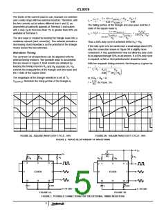
Test Circuit
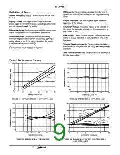
+10V
R
10K
R
10K
R
B
10K
L
A
4
5
6
7
8
9
3
SW
N.C.
1
ICL8038
11
R
R
TRI
10
12
2
SINE
C
3300pF
82K
-10V
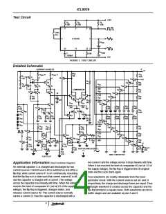
FIGURE 1. TEST CIRCUIT
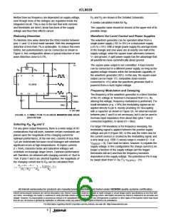
Detailed Schematic
6
CURRENT SOURCES
V+
R
4K
41
R
5.2K
R
B
R
A
EXT
32
EXT
R
11K
1
Q
8
1
5
Q
4
14
Q
Q
48
1
2
7
R
5K
8
Q
R
200
Q
3
33
47
R
39K
2
R
19
Q
6
Q
Q
Q
Q
Q
4
5
9
46
800
COMPARATOR
Q
R
34
375
45
R
20
Q
7
8
Q
10
44
Q
18
2.7K
Q
15
R
R
Q
35
46
40K
43
R
21
Q
330
17
Q
16
C
EXT
R
Q
42
9
10K
Q
5K
R
R
7B
7A
Q
41
10
R
33K
R
33K
R
33K
R
26
33K
R
30K
27
45
25
3
10K
15K
Q
11
Q
12
R
36
Q
Q
21
30
Q
20
1600
Q
13
Q
Q
22
31
Q
19
R
100
R
5
R
R
R
R
R
4
6
31
28
29
30
R
5K
Q
Q
Q
100 100
10
33K
33K
33K
33K
32
33
34
Q
22
49
R
Q
50
10K
R
R
R
37
R
13
16
1.8K
Q
51
43
27K
330
620
R
23
Q
Q
24
52
2.7K
R
27K
R
38
375
14
9
Q
Q
53
37
Q
Q
39
35
R
24
R
270
11
Q
Q
54
36
Q
Q
40
38
R
3
39
R
800
R
Q
Q
44
1K
Q
41
27K
28
55
Q
26
Q
23
27
200
12
R
R
R
470
Q
17
4.7K
12
15
56
2.7K
R
40
R
R
C
42
27K
EXT
82K
BUFFER AMPLIFIER
11
2
5.6K
Q
Q
29
25
R
18
4.7K
SINE CONVERTER
FLIP-FLOP
net-current I and the voltage across it drops linearly with time.
When it has reached the level of comparator #2 (set at 1/3 of
the supply voltage), the flip-flop is triggered into its original
state and the cycle starts again.
Application Information (See Functional Diagram)
An external capacitor C is charged and discharged by two
current sources. Current source #2 is switched on and off by a
flip-flop, while current source #1 is on continuously. Assuming
that the flip-flop is in a state such that current source #2 is off,
and the capacitor is charged with a current I, the voltage
across the capacitor rises linearly with time. When this voltage
reaches the level of comparator #1 (set at 2/3 of the supply
voltage), the flip-flop is triggered, changes states, and
releases current source #2. This current source normally
carries a current 2I, thus the capacitor is discharged with a
Four waveforms are readily obtainable from this basic
generator circuit. With the current sources set at I and 2I
respectively, the charge and discharge times are equal. Thus
a triangle waveform is created across the capacitor and the
flip-flop produces a square wave. Both waveforms are fed to
buffer stages and are available at pins 3 and 9.
4

 INTERSIL [ Intersil ]