ICL8038
o
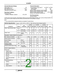
Electrical Specifications
V
= ±10V or +20V, T = 25 C, R = 10kΩ, Test Circuit Unless Otherwise Specified (Continued)
SUPPLY
A
L
ICL8038CC
ICL8038BC
ICL8038AC
TEST
CONDITIONS
PARAMETER
SYMBOL
MIN TYP MAX MIN TYP MAX MIN TYP MAX
UNITS
Sine Wave
Amplitude
V
R
R
= 100kΩ
0.2 0.22
-
0.2 0.22
-
0.2 0.22
-
xV
SINE
SINE
SUPPLY
%
THD
THD
= 1MΩ
-
2.0
5
-
1.5
3
-
1.0
1.5
S
(Note 4)
THD Adjusted
NOTES:
THD
Use Figure 4
-
1.5
-
-
1.0
-
-
0.8
-
%
2. R and R currents not included.
A
B
3. V
= 20V; R and R = 10kΩ, f 10kHz nominal; can be extended 1000 to 1. See Figures 5A and 5B.
A B
SUPPLY
4. 82kΩ connected between pins 11 and 12, Triangle Duty Cycle set at 50%. (Use R and R .)
A
B
5. Figure 1, pins 7 and 8 connected, V
= ±10V. See Typical Curves for T.C. vs V
.
SUPPLY
SUPPLY
6. Not tested, typical value for design purposes only.
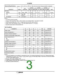
Test Conditions
PARAMETER
R
R
R
C
SW
1
MEASURE
A
B
L
Supply Current
10kΩ
10kΩ
10kΩ
10kΩ
10kΩ
10kΩ
10kΩ
10kΩ
10kΩ
10kΩ
10kΩ
10kΩ
3.3nF
3.3nF
3.3nF
3.3nF
Closed
Open
Current Into Pin 6
Frequency at Pin 9
Frequency at Pin 3
Frequency at Pin 9
Sweep FM Range (Note 7)
Frequency Drift with Temperature
Frequency Drift with Supply Voltage (Note 8)
Closed
Closed
Output Amplitude (Note 10)
Sine
10kΩ
10kΩ
10kΩ
10kΩ
10kΩ
10kΩ
10kΩ
10kΩ
10kΩ
10kΩ
10kΩ
10kΩ
3.3nF
3.3nF
3.3nF
3.3nF
3.3nF
Closed
Closed
Closed
Closed
Closed
Pk-Pk Output at Pin 2
Pk-Pk Output at Pin 3
Current into Pin 9
Triangle
Leakage Current (Off) (Note 9)
Saturation Voltage (On) (Note 9)
Rise and Fall Times (Note 11)
Output (Low) at Pin 9
Waveform at Pin 9
4.7kΩ
Duty Cycle Adjust (Note 11)
Max
50kΩ
~25kΩ
10kΩ
10kΩ
~1.6kΩ
50kΩ
10kΩ
10kΩ
10kΩ
10kΩ
10kΩ
10kΩ
3.3nF
3.3nF
3.3nF
3.3nF
Closed
Closed
Closed
Closed
Waveform at Pin 9
Waveform at Pin 9
Waveform at Pin 3
Waveform at Pin 2
Min
Triangle Waveform Linearity
Total Harmonic Distortion
NOTES:
7. The hi and lo frequencies can be obtained by connecting pin 8 to pin 7 (f ) and then connecting pin 8 to pin 6 (f ). Otherwise apply Sweep
HI
LO
2
Voltage at pin 8 ( / V
+2V) ≤ V
≤ V
SUPPLY
where V
is the total supply voltage. In Figure 5B, pin 8 should vary between
3
SUPPLY
5.3V and 10V with respect to ground.
8. 10V ≤ V+ ≤ 30V, or ±5V ≤ V ≤ ±15V.
SWEEP
SUPPLY
SUPPLY
9. Oscillation can be halted by forcing pin 10 to +5V or -5V.
10. Output Amplitude is tested under static conditions by forcing pin 10 to 5V then to -5V.
11. Not tested; for design purposes only.
3

 INTERSIL [ Intersil ]