EL5127, EL5227, EL5327, EL5427
Driving Capacitive Loads
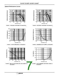
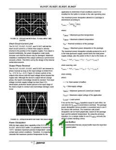
The EL5127, EL5227, EL5327, and EL5427 can drive a wide
range of capacitive loads. As load capacitance increases,
however, the -3dB bandwidth of the device will decrease and
the peaking increase. The buffers drive 10pF loads in
parallel with 10kΩ with just 1.5dB of peaking, and 100pF
with 6.4dB of peaking. If less peaking is desired in these
applications, a small series resistor (usually between 5Ω and
50Ω) can be placed in series with the output. However, this
will obviously reduce the gain slightly. Another method of
reducing peaking is to add a “snubber” circuit at the output.
A snubber is a shunt load consisting of a resistor in series
with a capacitor. Values of 150Ω and 10nF are typical. The
advantage of a snubber is that it does not draw any DC load
current or reduce the gain.
Power Supply Bypassing and Printed Circuit
Board Layout
As with any high frequency device, good printed circuit
board layout is necessary for optimum performance. Ground
plane construction is highly recommended, lead lengths
should be as short as possible, and the power supply pins
must be well bypassed to reduce the risk of oscillation. For
normal single supply operation, where the V - pin is
S
connected to ground, a 0.1µF ceramic capacitor should be
placed from V + pin to V - pin. A 4.7µF tantalum capacitor
S
S
should then be connected from V + pin to ground. One
S
4.7µF capacitor may be used for multiple devices. This same
capacitor combination should be placed at each supply pin
to ground if split supplies are to be used.
All Intersil U.S. products are manufactured, assembled and tested utilizing ISO9000 quality systems.
Intersil Corporation’s quality certifications can be viewed at www.intersil.com/design/quality
Intersil products are sold by description only. Intersil Corporation reserves the right to make changes in circuit design, software and/or specifications at any time without
notice. Accordingly, the reader is cautioned to verify that data sheets are current before placing orders. Information furnished by Intersil is believed to be accurate and
reliable. However, no responsibility is assumed by Intersil or its subsidiaries for its use; nor for any infringements of patents or other rights of third parties which may result
from its use. No license is granted by implication or otherwise under any patent or patent rights of Intersil or its subsidiaries.
For information regarding Intersil Corporation and its products, see www.intersil.com
12

 INTERSIL [ Intersil ]