CA3094, CA3094A, CA3094B
Typical Applications
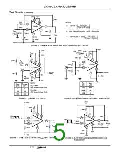
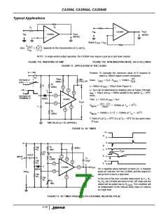
Z
Z
1
2
+
-
E
E
CA3094
OUT
(NOTE)
IN
E
E
CA3094
OUT
IN
-
(NOTE)
+
Where E
OUT
= E
IN
Z
E
2
OUT
------
here ----------------- = f
depends on the characteristics of Z and Z
1 2
Z
1
E
IN
NOTE: In single-ended output operation, the CA3094 may require a pull up or pull down resistor.
FIGURE 11A. INVERTING OP AMP
FIGURE 11B. NON-INVERTING MODE, AS A FOLLOWER
FIGURE 11. APPLICATION OF THE CA3094
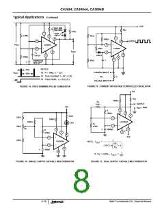
V+ = 18V
Problem: To calculate the maximum value of R required to
switch a 100mA output current comparator
S
1
R
18V
5µA
ABC
220kΩ
2kΩ
PULL UP
VOLTAGE A
-----------
= 3.6MΩ ≈
Given:
I
= 5µA, R
ABC
ABC
2/3V+
0
R
1
R
I = 500nA at I
ABC
= 100µA (from Figure 3)
I
100kΩ
5
7
+18
0
I = 5µA can be determined by drawing a line on Figure 3 through
I
I
I
o
8
I
= 100µA and I = 500nA parallel to the typical T = 25 C
ABC
curve.
B
A
+
2
3
A
VOLTAGE AT
TERMINAL 8
1N914
12V
CA3094
Then: I = 33nA at I
= 5µA
I
ABC
E
OUT
-
o
18V – 12V
33nA
R
R
= --------------------------- = 180MΩ at T = 25 C
MAX
MAX
A
C
6
4
R
2
o
= 180MΩ × 2 ⁄ 3† = 120MΩ at T = –55 C
220kΩ
A
o
o
† Ratio of I at T = 25 C to I at T = -55 C for any given value
I
A
I
A
of I
ABC
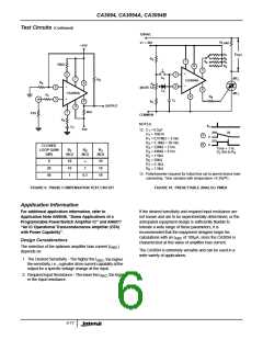
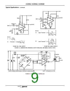
TIME DELAY (s) = RC (APPROX.)
FIGURE 12. RC TIMER
V+
0
A
0
V+
B
C
R
1
100
kΩ
220kΩ
0
1MΩ
3
/ V+
4
270
kΩ
D
0.01µF
D
E
7
0
R
INPUT
2
B
C
1
A
8
2.2MΩ
100
kΩ
0.5µF
V+
0
5
+
3
E
C
6
E
CA3094
OUT
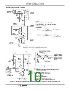
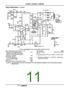
On a negative going transient at input (A), a negative
pulse at C will turn “on” the CA3094, and the output (E)
will go from a low to a high level.
1N914
2
-
12V
DC
100
kΩ
R
LOAD
2kΩ
4
100
kΩ
At the end of the time constant determined by C , R ,
1
1
R
3
R , R , the CA3094 will return to the “off” state and the
2
3
1MΩ
output will be pulled low by R
. This condition will
LOAD
be independent of the interval when input (A) returns
to a high level.
FIGURE 13. RC TIMER TRIGGERED BY EXTERNAL NEGATIVE PULSE
3-18

 INTERSIL [ Intersil ]