BBT3821
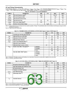
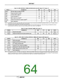
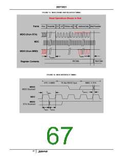
Table 115. MDIO INTERFACE TIMING (FROM IEEE802.3AE) (SEE Figure 15 TO Figure 17)
SYMBOL
PARAMETER
BBT3821 MDIO out delay from MDC
MIN
0
TYP
5.0
1.5
1.5
400
160
2
MAX
UNIT
ns
T
T
T
T
T
T
300
MDCD
Setup from MDIO in to MDC
Hold from MDC to MDIO in
10
ns
MDS
10
ns
MDH
(1)
Clock Period MDC
100
20
ns
MDC
(1)
MDC Clock HI or LO time
ns
MDV
(2)
Delay from last data bit to register update
Input Capacitance
T
Update
MDC
pF
C
10
MD
Note (1): The BBT3821 will accept a much higher MDC clock rate and shorter HI and LO times than the IEEE802.3 specification (section 22.2.2.11) requires. Such a
faster clock may not be acceptable to other devices on the interface.
Note (2): The BBT3821 MDIO registers will not be written until two MDC clocks have occurred after the frame end. These will normally count toward the minimum
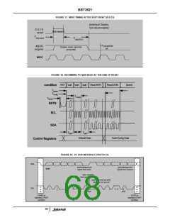
preamble before the next frame, except in the case of writing a RESET into [1,3,4].0.15, see Figure 17.
Table 116. RESET AND MDIO TIMING (SEE Figure 17)
SYMBOL
PARAMETER
MIN
TYP
2
MAX
UNITS
T
Reset bit Active width
Delay from Reset bit to first active preamble count
T
MDC
RSTBIT
MDRST
T
240
256
282
T
REFCLK
2
Table 117. RESET AND I C SERIAL INTERFACE TIMING (SEE Figure 18 AND Figure 24)
SYMBOL
PARAMETER
MIN
TYP
MAX
UNITS
µs
T
RSTN Active width
10
RESET
2
T
Delay from RSTN to I C SCL Start
2
10
30
ms
WAIT
T
I C ‘training’ (external reset)
T
CLAH_L
TRAIN
2
(1)
T
Period of I C SCL Clock Line (400kHz)
2.5
100
600
µs
CLAH_L
2
T
T
Setup from I C SDA Data Valid to SCL edge
ns
ns
pF
SCL_DAV
SDA_CLV
Setup, Hold from SDA for START, STOP
Input Capacitance
C
10
I2C
Note (1): Assuming RFCP-N clock is 156.25MHz, and register bits 1.8005.6:4 set for 400kHz (Table 20). SCL clock period scales with reference clock frequency. Also,
2
2
per the I C specification, the SCL ‘High’ time is stretched by the time taken for SCL to go high after the BBT3821 releases it, to allow an I C slave to demand
additional time. Any RC delays on the SCL line will add to the SCL ‘High’ time, in increments of approximately 100ns.
64

 INTERSIL [ Intersil ]