LXT971A 3.3V Dual-Speed Fast Ethernet Transceiver
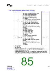
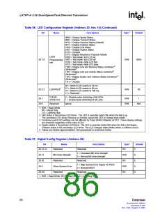
Table 56. LED Configuration Register (Address 20, Hex 14) (Continued)
Bit
Name
Description
Type 1
Default
0000 = Display Speed Status
0001 = Display Transmit Status
0010 = Display Receive Status (Default)
0011 = Display Collision Status
0100 = Display Link Status
0101 = Display Duplex Status
0110 = Unused
0111 = Display Receive or Transmit Activity
1000 = Test mode- turn LED on
1001 = Test mode- turn LED off
1010 = Test mode- blink LED fast
1011 = Test mode- blink LED slow
1100 = Display Link and Receive Status combined 2
(Stretched)3
LED3
20.7:4
R/W
0010
Programming
bits
1101 = Display Link and Activity Status combined 2
(Stretched)3
1110 = Display Duplex and Collision Status combined 4
(Stretched)3
1111 = Unused
00 = Stretch LED events to 30 ms.
01 = Stretch LED events to 60 ms.
10 = Stretch LED events to 100 ms.
11 = Reserved.
20.3:2
LEDFREQ5
R/W
00
PULSE-
0 = Disable pulse stretching of all LEDs.
1 = Enable pulse stretching of all LEDs.
20.1
20.0
R/W
R/W
1
STRETCH
Reserved
Ignore.
N/A
1. R/W = Read /Write
RO = Read Only
LH = Latching High
2. Link status is the primary LED driver. The LED is asserted (solid ON) when the link is up.
The secondary LED driver (Receive or Activity) causes the LED to change state (blink).
3. Combined event LED settings are not affected by Pulse Stretch Register bit 20.1. These display settings
are stretched regardless of the value of 20.1.
4. Duplex status is the primary LED driver. The LED is asserted (solid ON) when the link is full-duplex.
Collision status is the secondary LED driver. The LED changes state (blinks) when a collision occurs.
5. Values are relative approximations. Not guaranteed or production tested.
Table 57. Digital Config Register (Address 26)
Bit
Name
Reserved
Description
Type 1
RO
Default
26.15:12
Reserved
0
0
0
0
0
1 = Increased MII drive strength
0 = Normal MII drive strength
26.11
26.10
26.9
MII Drive Strength
Reserved
R/W
RO
Reserved
1 = Map Symbol Error Signal To RXER
0 = Normal RXER
Show Symbol Error
Reserved
R/W
RO
26.8:0
Reserved
1. R/W = Read /Write, RO = Read Only, LH = Latching High
86
Datasheet
Document #: 249414
Revision #: 002
Rev. Date: August 7, 2002

 INTEL [ INTEL ]