LXT971A 3.3V Dual-Speed Fast Ethernet Transceiver
6.0
Register Definitions
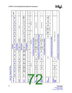
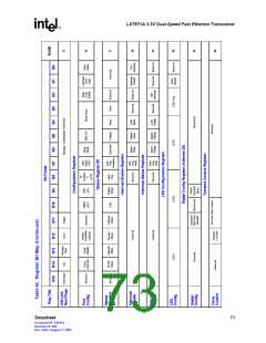
The LXT971A register set includes multiple 16-bit registers. Table 41 presents a complete register
listing. Table 42 is a complete memory map of all registers and Tables 43 through 58 provide
individual register definitions.
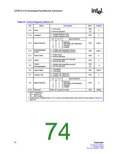
Base registers (0 through 8) are defined in accordance with the “Reconciliation Sublayer and
Media Independent Interface” and “Physical Layer Link Signaling for 10/100 Mbps Auto-
Negotiation” sections of the IEEE 802.3 standard.
Additional registers are defined in accordance with the IEEE 802.3 standard for adding unique chip
functions.
Table 41. Register Set
Address
Register Name
Bit Assignments
0
1
Control Register
Refer to Table 43 on page 74
Refer to Table 44 on page 75
Refer to Table 45 on page 76
Refer to Table 46 on page 76
Refer to Table 47 on page 77
Refer to Table 48 on page 78
Refer to Table 49 on page 79
Refer to Table 50 on page 79
Refer to Table 51 on page 80
Not Implemented
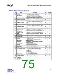
Status Register #1
2
PHY Identification Register 1
PHY Identification Register 2
Auto-Negotiation Advertisement Register
Auto-Negotiation Link Partner Base Page Ability Register
Auto-Negotiation Expansion Register
Auto-Negotiation Next Page Transmit Register
Auto-Negotiation Link Partner Received Next Page Register
1000BASE-T/100BASE-T2 Control Register
1000BASE-T/100BASE-T2 Status Register
Extended Status Register
3
4
5
6
7
8
9
10
15
16
17
18
19
20
21-25
26
27-29
30
Not Implemented
Not Implemented
Port Configuration Register
Refer to Table 52 on page 81
Refer to Table 53 on page 82
Refer to Table 54 on page 83
Refer to Table 55 on page 84
Refer to Table 56 on page 85
–
Status Register #2
Interrupt Enable Register
Interrupt Status Register
LED Configuration Register
Reserved
Digital Config Register
Refer to Table 57 on page 86
–
Reserved
Transmit Control Register
Refer to Table 58 on page 87
Datasheet
71
Document #: 249414
Revision #: 002
Rev. Date: August 7, 2002

 INTEL [ INTEL ]