LXT971A 3.3V Dual-Speed Fast Ethernet Transceiver
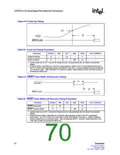
Figure 40. Power-Up Timing
v1
t1
VCC
MDIO,etc
Table 39. Power-Up Timing Parameters
1
Parameter
Symbol
Min
Typ
Max
Units
Test Conditions
Voltage threshold
Power Up delay2
v1
t1
–
–
2.9
–
–
V
–
–
300
µs
1. Typical values are at 25° C and are for design aid only; not guaranteed and not subject to production
testing.
2. Power-up delay is specified as a maximum value because it refers to the PHY guaranteed performance -
the PHY comes out of reset after a delay of No MORE Than 300 µs. System designers should consider this
as a minimum value - After threshold v1 is reached, the MAC should delay No LESS Than 300 µs before
accessing the MDIO port.
Figure 41. RESET Pulse Width and Recovery Timing
t1
RESET
t2
MDIO,etc
Table 40. RESET Pulse Width and Recovery Timing Parameters
1
Parameter
Symbol
Min
Typ
Max
Units
Test Conditions
RESET pulse width
RESET recovery delay2
t1
t2
10
–
–
–
ns
–
–
300
µs
1. Typical values are at 25° C and are for design aid only; not guaranteed and not subject to production
testing.
2. Reset Recovery Delay is specified as a maximum value because it refers to the PHY guaranteed
performance - the PHY comes out of reset after a delay of No MORE Than 300 µs. System designers
should consider this as a minimum value - After de-asserting RESET*, the MAC should delay No LESS
Than 300 µs before accessing the MDIO port.
70
Datasheet
Document #: 249414
Revision #: 002
Rev. Date: August 7, 2002

 INTEL [ INTEL ]