Configuration Specification
Page 47
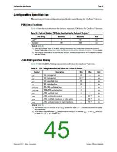
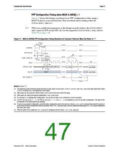
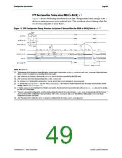
FPP Configuration Timing when DCLK to DATA[] = 1
Figure 17 shows the timing waveform for an FPP configuration when using a
MAX® II device as an external host. This waveform shows timing when the
DCLK-to-DATA[] ratio is 1.
1
When you enable decompression or the design security feature, the DCLK-to-DATA[]
ratio varies for FPP x8 and FPP x16. For the respective DCLK-to-DATA[] ratio, refer to
Table 50 on page 1–46.
Figure 17. DCLK-to-DATA[] FPP Configuration Timing Waveform for Cyclone V Devices When the Ratio is 1 (1)
tCF2ST1
tCFG
tCF2CK
nCONFIG
nSTATUS (2)
tSTATUS
(6)
tCF2ST0
tCLK
CONF_DONE (3)
t
CH tCL
tCF2CD
tST2CK
(4)
DCLK
tDH
Word 0 Word 1 Word 2 Word 3
Word n-2 Word n-1
DATA[15..0](5)
User Mode
User Mode
tDSU
High-Z
User I/O
(7)
INIT_DONE
tCD2UM
Notes to Figure 17:
(1) The beginning of this waveform shows the device in user mode. In user mode, nCONFIG
nCONFIG is pulled low, a reconfiguration cycle begins.
, nSTATUS, and CONF_DONE are at logic-high levels. When
(2) After power up, the Cyclone V device holds nSTATUS low for the time of the POR delay.
(3) After power up, before and during configuration, CONF_DONE is low.
(4) Do not leave DCLK floating after configuration. You can drive it high or low, whichever is more convenient.
(5) For FPP x16, use DATA[15..0]. For FPP x8, use DATA[7..0]. DATA[15..0] are available as a user I/O pin after configuration. The state of this
pin depends on the dual-purpose pin settings.
(6) To ensure a successful configuration, send the entire configuration data to the Cyclone V device. CONF_DONE is released high when the Cyclone V
device receives all the configuration data successfully. After CONF_DONE goes high, send two additional falling edges on DCLK to begin initialization
and enter user mode.
(7) After the option bit to enable the INIT_DONE pin is configured into the device, INIT_DONE goes low.
December 2013 Altera Corporation
Cyclone V Device Datasheet

 INTEL [ INTEL ]