Configuration Specification
Page 49
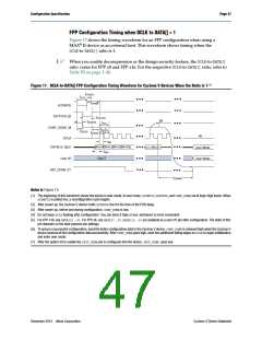
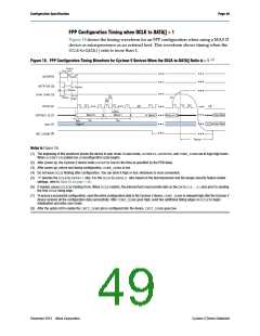
FPP Configuration Timing when DCLK to DATA[] > 1
Figure 18 shows the timing waveform for an FPP configuration when using a MAX II
device or microprocessor as an external host. This waveform shows timing when the
DCLK-to-DATA[]ratio is more than 1.
(1)
Figure 18. FPP Configuration Timing Waveform for Cyclone V Devices When the DCLK-to-DATA[] Ratio is > 1
tCF2ST1
tCFG
tCF2CK
nCONFIG
nSTATUS (2)
tSTATUS
tCF2ST0
CONF_DONE (3)
t
CL
tCF2CD
(7)
tST2CK
t
CH
DCLK (5)
DATA[15..0] (7)
User I/O
(6)
(4)
1
2
1
1
2
r
1
2
r
r
t
CLK
Word 0
Word 1
Word (n-1)
User Mod
User Mod
Word 3
t
t
tDSU
DH
DH
High-Z
(8)
INIT_DONE
tCD2UM
Notes to Figure 18:
(1) The beginning of this waveform shows the device in user mode. In user mode, nCONFIG, nSTATUS, and CONF_DONE are at logic high levels.
When nCONFIG is pulled low, a reconfiguration cycle begins.
(2) After power up, the Cyclone V device holds nSTATUS low for the time as specified by the POR delay.
(3) After power up, before and during configuration, CONF_DONE is low.
(4) Do not leave DCLK floating after configuration. You can drive it high or low, whichever is more convenient.
(5) “r” denotes the DCLK-to-DATA[] ratio. For the DCLK-to-DATA[] ratio based on the decompression and the design security feature enable
settings, refer to Table 50 on page 1–46.
(6) If needed, pause DCLK by holding it low. When DCLK restarts, the external host must provide data on the DATA[15..0] pins prior to sending
the first DCLK rising edge.
(7) To ensure a successful configuration, send the entire configuration data to the Cyclone V device. CONF_DONE is released high after the Cyclone V
device receives all the configuration data successfully. After CONF_DONE goes high, send two additional falling edges on DCLK to begin
initialization and enter user mode.
(8) After the option bit to enable the INIT_DONE pin is configured into the device, INIT_DONE goes low.
December 2013 Altera Corporation
Cyclone V Device Datasheet

 INTEL [ INTEL ]