Electrical Specifications
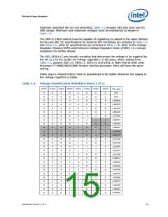
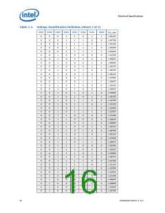
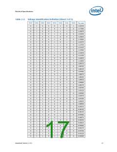
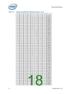
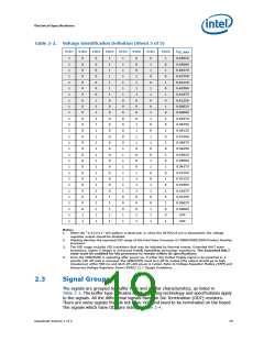
Table 2-2.
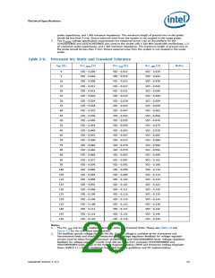
Voltage Identification Definition (Sheet 5 of 5)
VID7
VID6
VID5
VID4
VID3
VID2
VID1
VID0
V
CC_MAX
1
1
1
1
1
1
1
1
1
1
1
1
1
1
1
1
1
1
1
1
1
1
1
1
1
1
1
1
0
0
0
0
0
0
0
0
0
0
0
0
0
0
0
0
0
0
0
0
0
0
0
0
0
0
1
1
0
0
0
0
0
0
0
1
1
1
1
1
1
1
1
1
1
1
1
1
1
1
1
1
1
1
1
1
1
1
1
1
1
1
1
0
0
0
0
0
0
0
0
0
0
0
0
0
0
0
0
1
1
1
1
1
1
1
1
1
1
1
1
0
0
0
0
0
0
0
0
1
1
1
1
1
1
1
1
0
0
0
1
1
0
0
0
1
1
1
1
0
0
0
0
1
1
1
1
0
0
0
0
1
1
1
1
0
0
0
1
1
0
1
1
0
0
1
1
0
0
1
1
0
0
1
1
0
0
1
1
0
0
1
1
0
0
1
1
1
1
0
1
0
1
0
1
0
1
0
1
0
1
0
1
0
1
0
1
0
1
0
1
0
1
0
0
1
0.65625
0.65000
0.64375
0.63750
0.63125
0.62500
0.61875
0.61250
0.60625
0.60000
0.59375
0.58750
0.58125
0.57500
0.56875
0.56250
0.55625
0.55000
0.54375
0.53750
0.53125
0.52500
0.51875
0.51250
0.50625
0.50000
OFF
OFF
Notes:
1.
2.
3.
When the “11111111” VID pattern is observed, or when the SKTOCC# pin is deasserted, the voltage
regulator output should be disabled.
Shading denotes the expected VID range of the Intel Xeon Processor E7-8800/4800/2800 Product Families
processor.
The VID range includes VID transitions that may be initiated by thermal events, Extended HALT state
transitions, higher C-States or Enhanced Intel® SpeedStep technology transitions. The Extended HALT
state must be enabled for the processor to remain within its specifications
Once the VRM/EVRD is operating after power-up, if either the Output Enable signal is de-asserted or a
specific VID off code is received, the VRM/EVRD must turn off its output (the output should go to high
impedance) within 500 ms and latch off until power is cycled. Refer to Voltage Regulator Module (VRM) and
Enterprise Voltage Regulator-Down (EVRD) 11.1 Design Guidelines.
4.
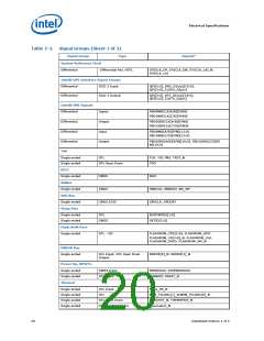
2.3
Signal Groups
The signals are grouped by buffer type and similar characteristics, as listed in
Table 2-3. The buffer type indicates which signaling technology and specifications apply
to the signals. All the differential signals have On Die Termination (ODT) resistors.
There are some signals that do not have ODT and need to be terminated on the board.
The signals which have ODT are listed in Table 2-4.
Datasheet Volume 1 of 2
19

 INTEL [ INTEL ]