Electrical Specifications
maximum specified VID are not permitted. Table 2-5 includes VID step sizes and DC
shift ranges. Minimum and maximum voltages must be maintained as shown in
Table 2-6.
The VRM or EVRD utilized must be capable of regulating its output to the value defined
by the new VID. DC specifications for dynamic VID transitions are included in Table 2-5
and Table 2-6, while AC specifications are included in Table 2-28. Refer to the Voltage
Regulator Module (VRM) and Enterprise Voltage Regulator-Down (EVRD) 11.1 Design
Guidelines for further details.
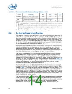
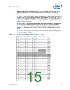
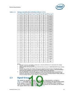
The VIO_VID[4:1] pins identify encoding that determine the voltage to be supplied by
the VR 11.1 to the socket Vio voltage regulators. In all cases, when reading from
Table 2-2, assume VID7=0, VID6=1, VID5=0, and VID0=0. Note that all Intel Xeon
Processor E7-8800/4800/2800 Product Families processor SKUs will have the same
setting.
Power source characteristics must be guaranteed to be stable whenever the supply to
the voltage regulator is stable.
Table 2-2.
Voltage Identification Definition (Sheet 1 of 5)
VID7
VID6
VID5
VID4
VID3
VID2
VID1
VID0
V
CC_MAX
0
0
0
0
0
0
0
0
0
0
0
0
0
0
0
0
0
0
0
0
0
0
0
0
0
0
0
0
0
0
0
0
0
0
0
0
0
0
0
0
0
0
0
0
0
0
0
0
0
0
0
0
0
0
0
0
0
0
0
0
0
0
0
0
0
0
0
0
0
0
0
0
0
0
0
0
0
0
0
0
0
0
0
0
0
0
0
0
0
0
0
0
0
0
0
0
0
1
1
1
1
1
1
1
1
1
1
1
0
0
0
0
0
0
0
0
1
1
1
1
1
1
1
1
0
0
0
0
0
0
0
0
1
1
1
0
0
0
0
1
1
1
1
0
0
0
0
1
1
1
1
0
0
0
0
1
1
1
1
0
0
0
0
0
1
1
0
0
1
1
0
0
1
1
0
0
1
1
0
0
1
1
0
0
1
1
0
0
1
0
1
0
1
0
1
0
1
0
1
0
1
0
1
0
1
0
1
0
1
0
1
0
1
0
1
0
OFF
OFF
1.60000
1.59375
1.58750
1.58125
1.57500
1.56875
1.56250
1.55625
1.55000
1.54375
1.53750
1.53125
1.52500
1.51875
1.51250
1.50625
1.50000
1.49375
1.48750
1.48125
1.47500
1.46875
1.46250
1.45625
1.45000
Datasheet Volume 1 of 2
15

 INTEL [ INTEL ]