Chipset Configuration Registers
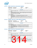
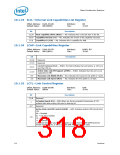
10.1.33 ILCL—Internal Link Capabilities List Register
Offset Address: 01A0–01A3h
Attribute:
Size:
RO
32-bit
Default Value:
00010006h
Bit
Description
31:20
19:16
15:0
Next Capability Offset (NEXT) — RO. Indicates this is the last item in the list.
Capability Version (CV) — RO. Indicates the version of the capability structure.
Capability ID (CID) — RO. Indicates this is capability for DMI.
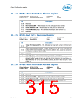
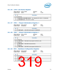
10.1.34 LCAP—Link Capabilities Register
Offset Address: 01A4–01A7h
Attribute:
Size:
R/WO, RO
32-bit
Default Value:
00012841h
Bit
Description
31:18
17:15
Reserved
Reserved
L0s Exit Latency (EL0) — R/WO. This field indicates that exit latency is 128 ns to
less than 256 ns.
14:12
11:10
Active State Link PM Support (APMS) — R/WO. Indicates that L0s and L1 are
supported on DMI.
9:4
3:0
Maximum Link Width (MLW) — RO. Indicates the maximum link width is 4 ports.
Maximum Link Speed (MLS) — RO. Indicates the link speed is 2.5 Gb/s.
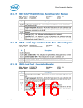
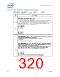
10.1.35 LCTL—Link Control Register
Offset Address: 01A8–01A9h
Attribute:
Size:
R/W
16-bit
Default Value:
0000h
Bit
Description
15:8
7
Reserved
Extended Synch (ES) — R/W. When set, forces extended transmission of FTS
ordered sets when exiting L0s prior to entering L0.
6:2
Reserved
Active State Link PM Control (ASPM) — R/W. Indicates whether DMI should enter
L0s.
00 = Disabled
01 = L0s entry enabled
10 = Reserved
1:0
11 = Reserved
Corporate Only: The value of this register is used unless the DMI ASPM Override
Enable register is set, in which case the DMI ASPM Override is used.
318
Datasheet

 INTEL [ INTEL ]