Thermal Specifications and Design Considerations
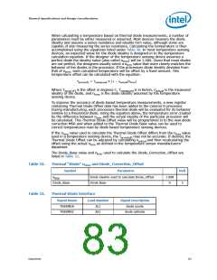
temperature. Transistor Model parameters (Table 31) have been added to support
thermal sensors that use the transistor equation method. The Transistor Model may
provide more accurate temperature measurements when the diode ideality factor is
closer to the maximum or minimum limits. This thermal "diode" is separate from the
Thermal Monitor's thermal sensor and cannot be used to predict the behavior of the
Thermal Monitor.
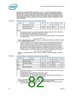
Table 30.
Thermal “Diode” Parameters using Diode Model
Symbol
IFW
Parameter
Min
Typ
Max
Unit
Notes
Forward Bias Current
Diode Ideality Factor
Series Resistance
5
—
200
1.050
6.24
µA
-
1
n
1.000
2.79
1.009
4.52
2, 3, 4
2, 3, 5
RT
Ω
NOTES:
1.
2.
3.
4.
Intel does not support or recommend operation of the thermal diode under reverse bias.
Characterized across a temperature range of 50 - 80 °C.
Not 100% tested. Specified by design characterization.
The ideality factor, n, represents the deviation from ideal diode behavior as exemplified by
the diode equation:
I
FW = IS * (e qV /nkT –1)
D
where IS = saturation current, q = electronic charge, VD = voltage across the diode, k = Boltzmann Constant,
and T = absolute temperature (Kelvin).
5.
The series resistance, RT, is provided to allow for a more accurate measurement of the
junction temperature. RT, as defined, includes the lands of the processor but does not
include any socket resistance or board trace resistance between the socket and the
external remote diode thermal sensor. RT can be used by remote diode thermal sensors
with automatic series resistance cancellation to calibrate out this error term. Another
application is that a temperature offset can be manually calculated and programmed into
an offset register in the remote diode thermal sensors as exemplified by the equation:
Terror = [RT * (N-1) * IFWmin] / [nk/q * ln N]
where Terror = sensor temperature error, N = sensor current ratio, k = Boltzmann Constant, q = electronic
charge.
Table 31.
Thermal “Diode” Parameters using Transistor Model
Symbol
IFW
Parameter
Min
Typ
Max
Unit
Notes
Forward Bias Current
Emitter Current
5
—
—
200
200
µA
µA
1, 2
IE
5
nQ
Transistor Ideality
0.997
0.391
2.79
1.001
—
1.005
0.760
6.24
3, 4, 5
3, 4
Beta
RT
Series Resistance
4.52
Ω
3, 6
NOTES:
1.
2.
3.
4.
5.
Intel does not support or recommend operation of the thermal diode under reverse bias.
Same as IFW in Table 30
Characterized across a temperature range of 50 – 80 °C.
Not 100% tested. Specified by design characterization.
The ideality factor, nQ, represents the deviation from ideal transistor model behavior as
exemplified by the equation for the collector current:
/n
I
C = IS * (e qVBE kT –1)
Q
Where IS = saturation current, q = electronic charge, VBE = voltage across the transistor base emitter junction
(same nodes as VD), k = Boltzmann Constant, and T = absolute temperature (Kelvin).
The series resistance, RT, provided in the Diode Model Table (Table 30) can be used for
more accurate readings as needed.
6.
82
Datasheet

 INTEL [ INTEL ]